

All of the credit for the design of the mechanical test frame has to go to CrazyBlackStone. The step-by-step instructions can be found here. While following these instructions, I found that some of the materials listed were inaccurate and incomplete, so I have recreated a list of materials that I used. This list can be found below, in the Materials section. Although some of the items needed for construction were inaccurate, the directions for building the test rig were very easy to follow. The electronics were a different story.
The directions for the electronics section said that you didn’t need any prior experience to be able to reproduce this, but I disagree. I have absolutely no experience building electronics, and I thought the instructions for the electronics section were quite vague and incomplete. For this reason, I went back to the first design of the project and just tried to recreate the more simple version of the wire diagram. I included a more complete list of materials below, which will allow you to recreate this project if you’re starting completely fresh. In the Electronics Assembly section below, I will describe my process of trying to get the test frame functioning.
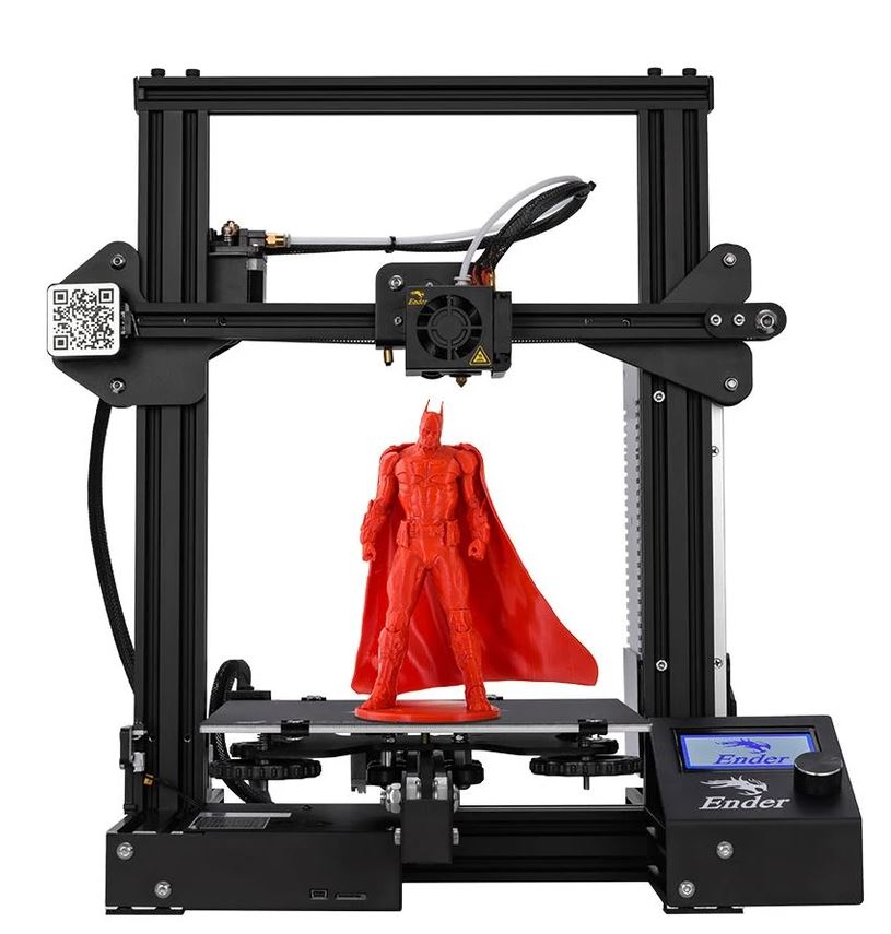
First, a Creality Ender 3 printer was used to fabricate all of the parts for the test frame assembly. The STL files can all be found here. The printed parts all utilized PLA with 80% grid infill, with exception of the grips and compression platens, which were 100% infill. 
I designed compression platens for this project to allow for testing of compression cylinders. STL files are not supported through this website, so an engineering drawing is provided so they can be recreated. This was just an extremely simple design so that small samples could be printed and tested, other platen designs could be used. If you want to test samples in tension, this webpage has an STL file that is compatible with this test frame.-


There are two versions of this mechanical test frame that have been published by CrazyBlackStone. The first version is much simplier, and the second version is much more advanced. For this project, I used the second version for the construction of the test frame. As for the electronics, like I said before, I am completely new to this world, so I started with high hopes of reproducing version two’s custom PCB, but failed. Defeated, I then attempted to reproduce version one’s electronics component. Again I was unsuccessful, but I would like to share my lessons, in case someone else would like to attempt this project.
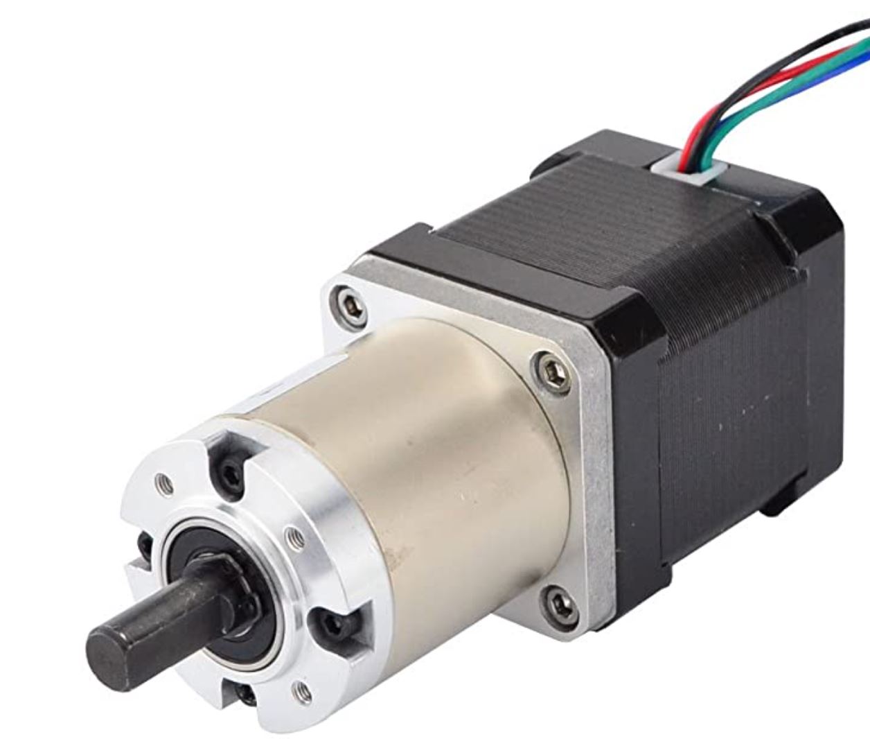
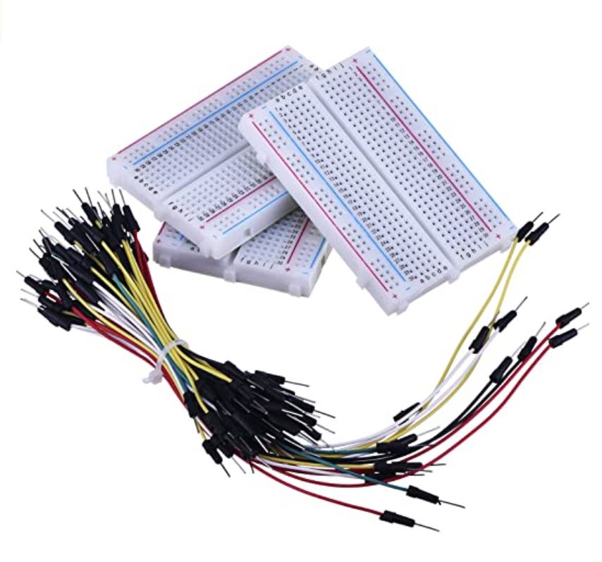
After gathering everything for version two’s project and realizing I was over my head, I decided to start off simple with a solderless breadboard. I recreated the tutorial’s that can be found on my main webpage in the Intermediate section. First, I was able to get my planetary gearbox stepper motor functioning. That tutorial can be found at this link. Next, I followed a tutorial to calibrate my load cell. I created the wire diagrams below from the two tutorials. I was successful at getting each of these circuits working, so logically, I moved on to combine the two.

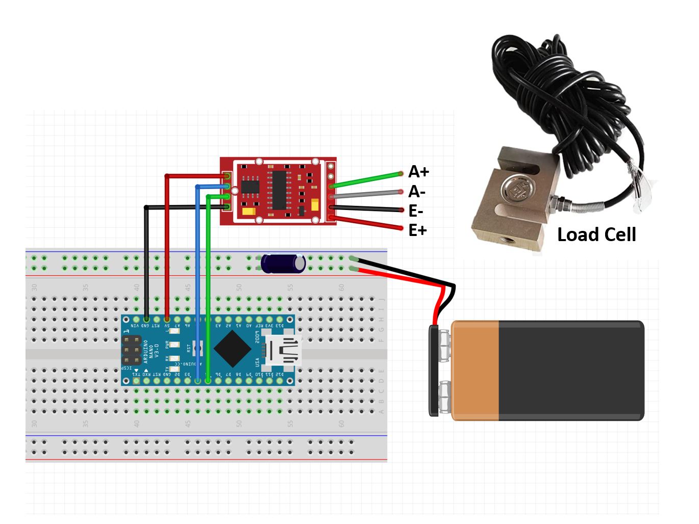
I used version one of CrazyBlackStone’s Instructable’s page to try and combine the two components. I was unsuccessful. Below is the wire diagram that I tried to recreate. The Arduino code can also be found at this link.

After my failure with version one, I decided not to give up just yet. I thought that since I had all of the materials for the more advanced version two, I might as well try. This version utilizes a custom PCB, which I ordered through JCLPCB. The files for the PCB can be found here. Since a PCB is used, I had to learn how to solder with this YouTube video.
I constructed the entire custom PCB, seen in the picture below. The instructions for the Arduino code can be found on the version two webpage. I was never able to get this version of the electronics to function. Although I was not able to have a fully functioning product at the end of this class, I still feel like I learned a lot from the process. I encourage someone with more experience with electronics than me, to give this project a try.
