
I’m Katie, a Mechanical Engineering PhD student at Duke University, and I research 3D metal printed lattice architectures for orthopedic applications. I utilize Selective Laser Melting (SLM) to fabricate the metal samples, which is an extremely expensive and labor intensive process that requires additional costly equipment to prepare samples and test their mechanical properties.
For my Experimental Design and Research Methods course, I have created an alternative method for testing the mechanical performance of lattice structures that is less expensive than metal printed samples. This project includes three parts: 1) constructing a 3D printed mechanical test frame, 2) printing Polylactic Acid (PLA) lattice architectures with Fused Filament Fabrication (FFF), and 3) testing the mechanical performance of PLA lattice structures.

Figure 1. Trabecular bone structure [4]
Personalized medicine and precision medicine are the current buzzwords in the medical community for improving patient care. Patient–specific orthopedic implants are one of the technologies that have been successfully implemented into this new area of medicine. Advances in medical imaging, computer aided design software, and additive manufacturing technologies have made it possible for unique implants to be increasingly affordable and accessible [1]. The advances in additive manufacturing have also allowed for improving the design of orthopedic implants all together.
Additive manufacturing enables the ability to create extremely complex structures that are not capable of being manufactured by traditional means. These complex and periodic structures are called lattices and come in many different designs [2, 3]. Lattice structures have recently been implemented into orthopedic implants because of their similarities to the microstructure of native bone. Figure 1 shows the natural porous structure of trabecular bone, which can be attributed to its unique material properties. Not only is bone as strong as cast iron but is a fraction of the mass, which is what lattice structures aim to imitate [5]. Titanium and titanium alloys are common materials used for these orthopedic implants because of their biocompatibility, corrosion resistance, low density [6]. In addition to 3D printing allowing the ability to fabricate these lattice structures to mimic the microstructure of bone, it also allows for the structure to be tailored to each patient’s anatomy [2]. Therefore, lattice structure design is critical to optimize for each implant to ensure failure does not occur.
The most common cause of titanium implant failure is loosening of the implant over time, which requires the need of revision surgery. One of the causes of implant loosening is stress shielding. This occurs when an implanted device being much stiffer than the surrounding bone, which causes the implant to bare the majority of forces acting upon that location. Over time, the native bone will atrophy, and as a result, the implant will loosen and eventually fail. These additively manufactured lattice structures have decreased stiffness, in comparison to the traditionally solid implants, which reduces stress shielding. By designing orthopedic implants with lattice architectures, you not only reduce the risk of loosening implants by decrease the stiffness, as stated above, but the porous lattice structure allows for boney ingrowth to occur. This osseointegration improves the implant’s stability over time, as more bone grows through the implant, reducing the risk of any stress shielding [2].

Figure 2. Stryker’s Trident II Tritanium 3D printed acetabular system.
Additively manufactured metallic lattice structures have recently been implemented into commercial orthopedic implants by some of the biggest names in the medical implant industry including, Stryker, Smith and Nephew, DePuy Sythesis, and Medacta. On the left, see images of Stryker’s commercially available acetabular cups (Figure 2).
There are over forty-four different types of lattice structures, and each of these can be manipulated by changing different properties [4]. These properties include: porosity, wall thickness/strut diameter, unit cell size, linear or radial gradients of these properties, laser settings, post-processing, and other endless possibilities. In order to optimize the design of each unique implant, and choose the most suitable lattice structure, these architectures need to be fully understood mechanically. These structures could, in theory, be tested with Finite Element Method (FEM) modeling, but from experience, many FEM software packages have difficulties modeling such complex structures. Currently, in the Gall Lab at Duke University, multi-axial loading research of a limited number of SLM printed titanium lattice structures has been initiated (Figure 3) but has barely skimmed the surface of characterizing the array of possible design possibilities. Although SLM printing is the ideal technology for manufacturing metallic lattice structures, it is expensive, slow, and manually demanding [4]. Time, money, and manpower are the limiting factors in being able to accomplish this abundant amount of research.

Figure 3. Single Unit Cell of A) Gyroid, B) Octet Truss, and C) Stochastic lattice architectures from 3Dxpert.
The solution to this problem is an FFF Printer. It is affordable, easily accessible, the material is inexpensive, and any additional machines required to prepare and test the samples are also orders of magnitude cheaper. Obviously, PLA is a much weaker material than titanium, so this allowed me to utilize a mechanical test frame that I constructed with 3D printed parts for a couple hundred dollars.
This project would allow prototyping of lattice structures to compare mechanical performance to find exceptional designs that should be researched further with metal fabrication.
Load Cell: The S-beam load cell is used in the mechanical test frame built for this project. A load cell is a transducer that converts force to an electrical signal, which allows for force data to be stored in a data file and analyzed. Load cell’s work by using strain gauges arranged in Whetstone Bridge Amplifier Circuits. The components are summarized below:
- Strain Gauge:
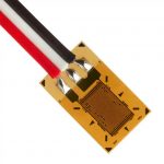
Strain Gauge
- Strain gauges are flexible polymer sheets with resistive wire patterned on top. When the strain gauge flexes, the resistance varies.
- Strain is caused by an applied force and resistance varies with strain, which means force can be calculated by resistance.
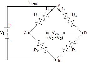
Wheatstone Bridge Circuit
- A circuit composed of two series parallel arranged resistances connected by a voltage supply and ground. There is no voltage produced when the bridge is balanced. A typical Wheatstone Bridge Circuit is shown to the right.
- A strain gauge is applied to at least on corner to make a load cell.
- The voltage variability across the Wheatstone Bridge is small, so this signal needs to be amplified in order to differentiate small changes in applied forces.
- Operational Amplifiers, or Op-Amps, amplifies the output voltage signal. This signal is mathematically expressed by:
Vo = Av (V2 – V1)

Op-Amp
Vo = output voltage
Av = op-amp gain
V1 = inverting input
V2 = non-inverting input
- The instructional video linked here explains all of these concepts and shows an example of their application.
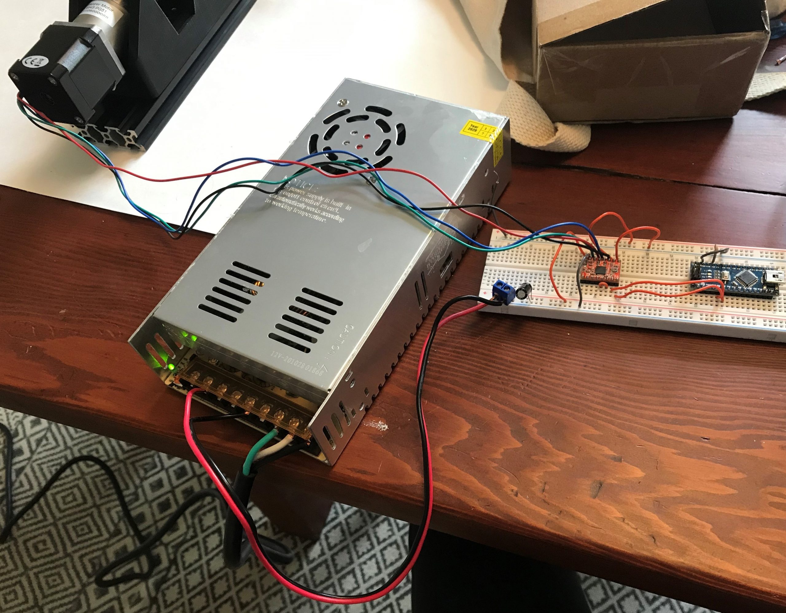
I am a complete novice when it comes to electronics. These two wire diagrams are similar to what the final project will utilize. I went through the tutorials below before starting this project, and I found them extremely helpful. I suggest you visit these websites and follow along, if you are new too.
- Stepper Motor with Arduino Tutorial:
- The link above shows how to get a stepper motor running.
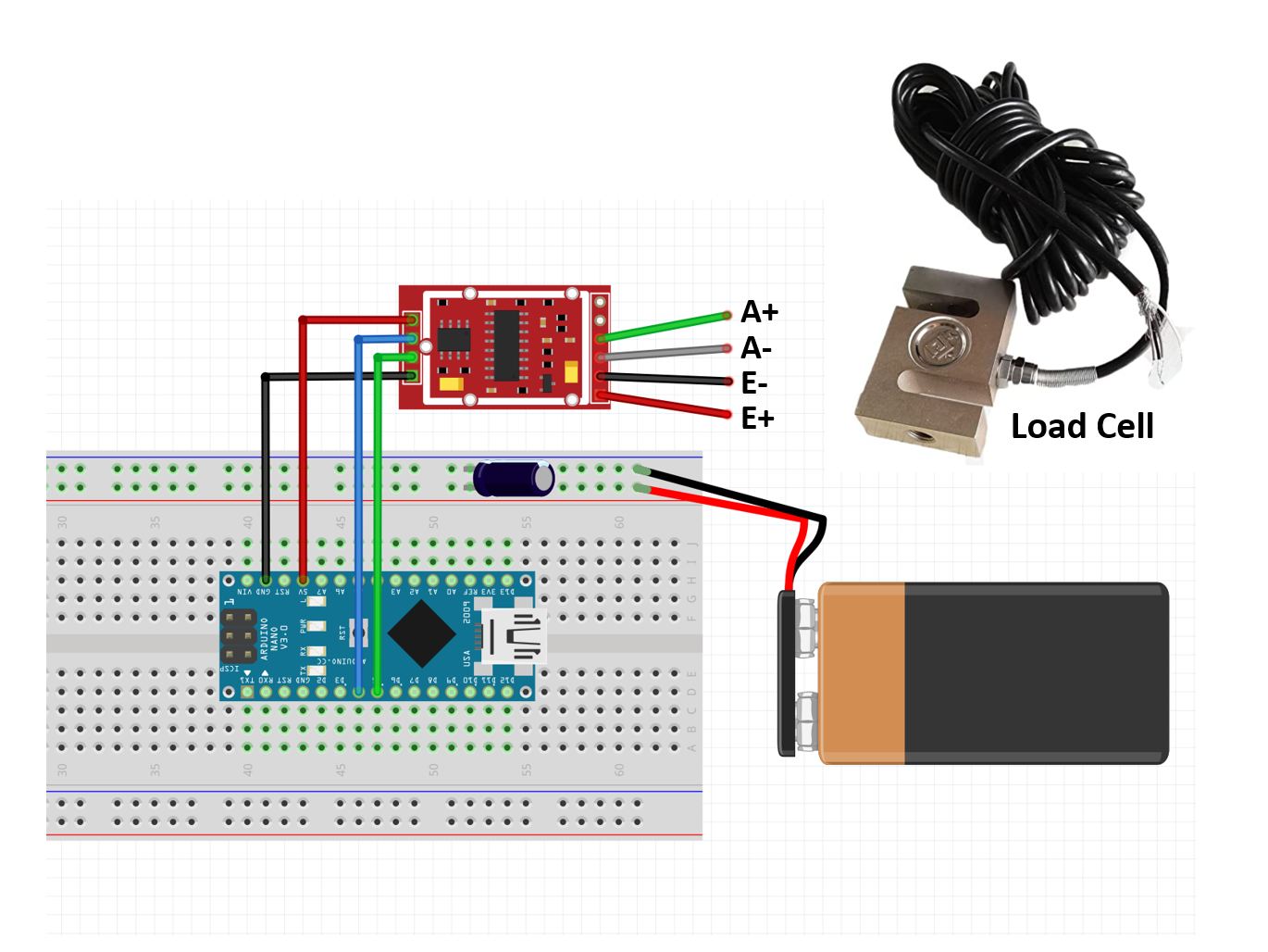
- I created the diagram below to include an Arduino nano, which is the device I used for my setup. Otherwise, I followed the tutorial’s directions to get my stepper motor running.

- Load Cell with Arduino Tutorial:
- The video in the link above goes into detail about how load cells work, which was discussed in the ‘Beginner’ section. It then goes through a step-by-step process for wiring a load cell, arduino, and load cell amplifier. It also shows how to calibrate your load cell.
- I created the sketch below so that you can recreate this wiring diagram without having to pause the video.


- Lattice PLA printing
- Unfortunately, I didn’t have much success printing the lattice structures with the FFF printer. The scale of the clinically relevant lattice structures is too small for the resolution of the Creality Ender 3 printer.
- I attempted to print the following lattice structures:

- I varied different printing parameters including layer height and print speed to try and get the structures to form. I also tried calibrating my printer, by following the directions in this video, but still did not have any luck. I think this small strut size is not ideal for this type of printer technology.
- All of the lattices are unable to even form, with the exception of the 65% porous gyroid. The quality of the print is low, as seen in the picture below.

- Since the majority of PLA lattice samples were unsuccessful, I did not complete mechanical testing on this cohort.
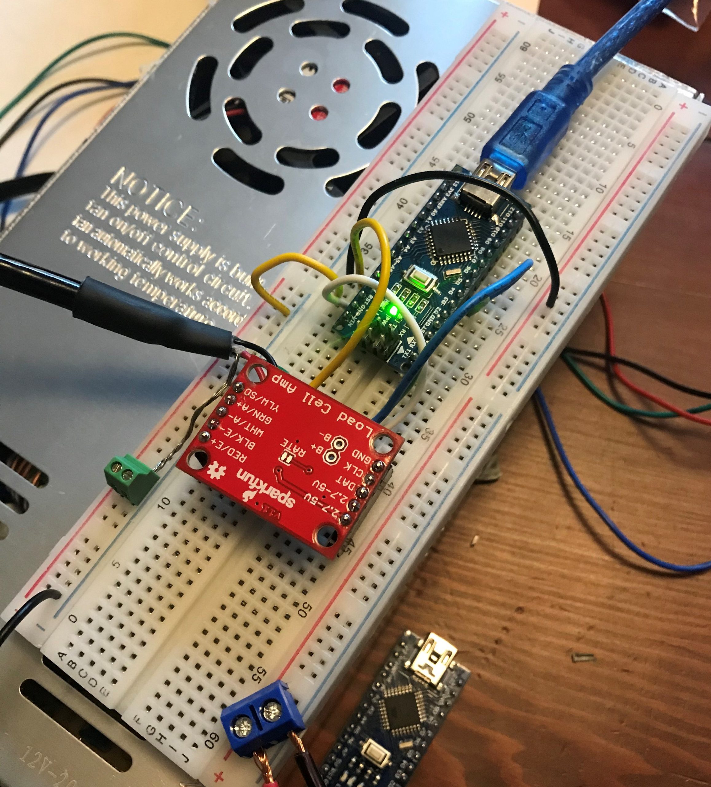
Mechanical Test Frame:

- Instructions for constructing the mechanical test frame :
- This link directs you to a supplemental page that I created to help recreate this test rig.
- Selective Laser Melting:
- This video below is a brief summary of SLM printing. I cover the parts of the printer, show the printing process, and show the final product.
- Mechanical Testing Metal Lattice Structures:
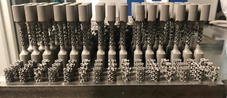
- I used Duke University’s SLM metal printer to fabricate three different architectures at three different clinically relevant porosities. These are the same porous structures that I attempted to print with the FFF printer. The list of samples can be seen below.
- These samples were printed with the titanium alloy, Ti6Al4V – Grade 23, with the optimized printing parameters of laser power =145 W and laser scan speed = 1000 mm/s. These printing parameters were developed by the Gall lab group [7].

- The mechanical testing of metal lattice structures requires an extremely large load cell. For my research, I used a MTS 809 test frame with a 250 kN load cell.
- I completed static testing of four loading modes: tension, compression, shear, and torsion.
- During these mechanical tests, I collect force (N) and displacement (mm) data. From this information, I am able to calculate: stress (MPa), strain, Young’s modulus (GPa), yield strength (MPa), and toughness (MJ/m³).
- The equations to calculate these mechanical properties are:
- Stress = Force / Cross-Sectional Area
- Strain = Change in Length / Original Length
- Young’s Modulus = Stress / Strain (The slope of the linear region of the Stress-Strain plot)
- Yield Strength = 0.2% offset method
- Toughness = Area under the stress strain curve
- I am planning on publishing this data as part of my PhD research. Since this data that I collected has not yet been peer reviewed, I am not going to share actual values on this page, but an example of a Stress-Strain curve from the data I collected from a static compression test of a single lattice architecture at three different porosities is below.

Hi, I’m Katie! It’s so nice to meet you.

Katie Nelson
My Education and Work Experience:
I am a second year mechanical engineering PhD student at Duke University. I have gotten this opportunity to advance my education thanks to an amazing scholarship from the Air Force Research Laboratory (AFRL), where I have worked as a Research Biomedical Engineer since 2015. I went to work for AFRL right after graduating with my Bachelor’s of Science in Biological Engineering from The University of Missouri-Columbia (M-I-Z!). I spent four years at AFRL studying radiofrequency bioeffects, which was honestly something I never saw myself doing, but extremely interesting.
Graduate Research:
I did a bit of a 180° turn on research topics when I started graduate school. I have always been interested in biomechanics, for that reason, I started working for Dr. Ken Gall’s lab group. My research has focused on mechanical performance of 3D printed metal lattice structures of orthopedic applications. I have gained countless skills since starting my grad school journey, including CAD design, selective laser melting additive manufacturing, and mechanical testing. I hope to utilize this newly acquired knowledge to help wounded soldiers, when I go back to work for the Department of Defense after graduation.
If you’re interested in learning more about my research or are interested in a collaboration, find me on LinkedIn.