Project Overview

Welcome to my subproject page! This is Mike Cui. The goal of my project is to achieve labyrinth tackling, which essentially is a demonstration of observing a way through a maze from start to finish. There are in general two strategies to address the problem. One is to map the entire maze so that the robot can solve it before entering it. From another perspective, the robot looks for an exit by collecting the data of the environment inside the maze in the middle of its voyage. The concentration of my part of the project will be the latter.

In a large scope, the application of this type of maze-solving robot can be useful in situations like fire accidents, earthquakes, or other natural disasters where maze mapping is not practical.

For the scope of this project, the computer vision algorithm aims to help a storage or warehouse robot to find a path to the exit (which can be a loading area, in this case) with great precision and without human interactions. If you want to know more about my team’s grand project, go to our page!

For the maze of our project, there will be lines on the ground and walls on the sides, for which the lines are utilized as pathways and the walls set the constrained space for the robot to move. There might be obstacles along the way to test out the robot functionality of object detection, which will be part of my teammate’s work. The picture on the left basically demonstrates the idea.

Learning Objectives

The objective of this project is to build and code a motorized car that uses a camera to see so it can learn and solve a maze. While completing this project, you will learn the following:

  • Data storage
  • Motor control
  • Autonomous driving
  • Computer vision
  • Image processing

Project Implementation

Maze Exploration

My part of the project can be broken down to two main components. The first step is to explore the maze. And to achieve that, we need our robot to be able to track the path line automatically. If you are interested in accomplishing line-tracking function with Jetson Nano robot on your own, you can follow the detailed instruction below.

First things first, the hardware. You need to have the Waveshare JetBot 2GB AI Kit AI Robot Based on Jetson Nano 2GB Developer Kit, click the link and you can find every component you need.

Here is a video on assembling the hardware.

The Jetbot in this video uses a WiFi antenna, but we will be using a WiFi Dongle instead.

Step 1 – Flash JetBot image onto SD card

  1. Download the the expandable JetBot SD card image jetbot-043_nano-2gb-jp45.zip.
  2. Connect the SD card to the PC via card reader.
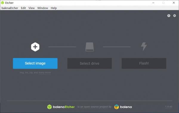
  3. Using Etcher, select the jetbot-043_nano-2gb-jp45.zip image and flash it onto the SD card.
Step 2 – Boot Jetson Nano
  1. Insert the SD card into your Jetson Nano (the micro SD card slot is located under the module).

  2. Connect the monitor, keyboard, and mouse to the Nano.
  3. Power on the Jetson Nano by connecting the micro USB charger to the micro USB port.
STEP 3 – Connect Jetbot to WIFI
  1. Log in using the user: jetbot and password: jetbot.
  2. Connect to a WiFi network using the Ubuntu desktop GUI. 
  • In order to reduce memory, the new version of the image has disabled the graphical interface, you need to use the command line to connect to WiFi.
sudo nmcli device wifi connect <SSID> password <PASSWORD>
 sTEP 4 – Access JetBot via Web
  1. Shut down JetBot by the command line. 
  2. sudo shutdown now
  3.  Start Jetson nano again. After booting, Ubuntu will automatically connect WIFI, the IP address is also displayed on OLED.
  4. Navigate to http://<jetbot_ip_address>:8888 from your desktop’s web browser.
  5. Sign in using the password: jetbot.
You will be presented with a view similar to the following.
 
For more details of how to do software setup, please look into the websites below.
  1. Using SD Card Image – JetBot
  2. Software Setup · NVIDIA-AI-IOT/jetbot Wiki (github.com)

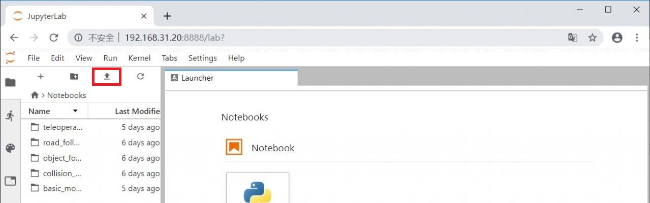
When you are able to access Jetbot using your own laptop through WiFi, download the code for data collection here. And upload the code by clicking the button in the red box shown in the figure blow.

The annotation in the code will tell you how to do the data collection.

HINTS

When you collect the data, it is recommended that you select the end point that is not too far from the starting point. Apart from that, you can also take several pictures in one place from different angles; and after you are done with one place, you can move the robot slightly forward to proceed capturing more pictures.

Do not over collect the data, less than 300 images for each class is enough. Otherwise, you will receive runtime error when you train your model. 

After you finished collecting the data and have your data zip file, download the code for training your deep learning model here.

Follow the annotation and you could be able to train your model.

HINTS

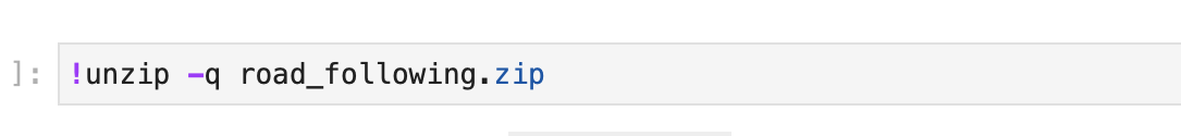
If you already have your data_cones folder exist, then do not run this line of code.

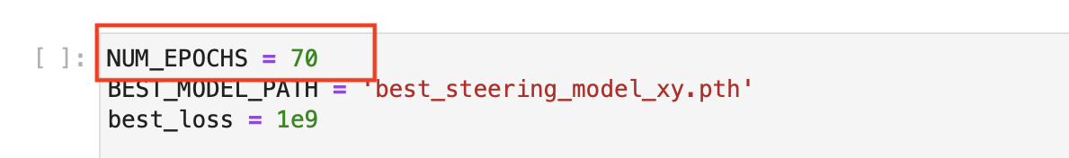
If you have runtime error when you are training your  model, you can decrease the number of epochs of training the model. This is because the 2 GB Jetson Nano we use here has a very low memory.

After you have your model trained, you can download the code for moving the Jetbot here.

Follow the annotation, you will be able to move your Jetbot.
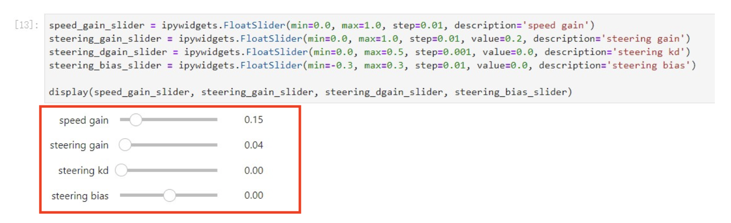
HINTS

When you see the sliders popping up, you may try adjusting parameters starting with low values, say speed gain starting with 0.1 and steering gain with 0.01. Check how smooth the robot moves. If the movement is clunky or deviating, try to play with kd as well as steering bias. After the robot obtains a steady movement, you can then increase the forward speed and corresponding PID parameter settings.


After successfully training the model, the robot should be able to track the line itself as the video demonstrates below.

Maze Mapping

The second step is then to map the maze. This section is to provide people who are interested in finishing the grand project with an idea. The maze mapping process is a fairly significant part of the project in terms of finding the optimal path after exploring the labyrinth. 

When the robot is in the middle of exploring the maze, we also set up a subscriber to obtain the data from the encoder feeds. The encoder basically gives tow flows of numbers, one for the left wheel, and one for the right. The numbers present the distance that the robot travels. With that data and some mathematical transformation, we can generate a trace that describes the movement of the robot as you can see in the middle picture.

Here we will need some reshape, we basically want to turn that single line trace (the middle picture) to an actual path with visible boundaries (the right one) so that my teammate Santiago’s algorithm can interpret it. There are various methods to do so, here we added an offset to the original trace so that the picture looks more like the maze we see in real life. And then after all that, we can publish that picture to the algorithm to help find the shortest path.

Challenges

Here we also want to address the challenges that you may encounter when you take over the project. First of all, you may want to tune the robot accordingly to make sure it does not deviate from the line. Once it deviates, it will be super difficult for the robot to make it back the track.

Another challenge is to acquire robot’s travel direction from encoder feeds. As we know, the encoder only gives a flow of numbers that present the distance. So finding a way to extract robot’s moving direction is a critical step to obtain usable x, y coordinates.

And finally, the robot is inevitably going to wobble a lot while traveling, generating plenty of noise. And with that noise you may not be able to get straight lines in the map when you try to graph them. Thus filtering out the noise is also essential from the perspective of this part of the project.

Necessary Skills

There are different levels of skill sets that you need to possess in order to accomplish the project.