
Motivation
Lightweight lattice structures have revolutionary potential in aerospace, automotive, and biomedical applications. These complex periodic can achieve exceptional strength-to-weight ratios, making them ideal for applications where weight is critical.
In aerospace, lattice structures are already being used in a variety of ways to replace classic solid component with porous more lightweight ones. Studies have shown that replacing solid parts with lattice infills can reduce the weight of aircraft door hinges and brackets by roughly 25–45%, and UAV ribs by nearly 60%, while maintaining sufficient strength and stiffness. Lattice materials are also being explored for morphing wing skins and other adaptive structures, where their low density and tunable mechanical response directly translate to improved efficiency and performance in weight-critical aerospace systems [1].
In biomedical engineering, lattice structures are increasingly used in orthopedics and tissue engineering. Gyroid lattices, in particular, offer extremely high surface area, making them well suited as bone substitutes and implant scaffolds. Their interconnected porous architecture enables bone to grow into and around the lattice, a process known as osseointegration. For these applications, it is crucial to identify lattice designs that provide both adequate surface area and an effective stiffness that closely matches that of natural bone, in order to promote stable integration and reduce stress shielding. [2]
In Automotive design, gyroid lattice structures are being looked at specifically for their energy absorption. By introducing grading into the lattice; making the top of the gyroid more porous than the bottom, it is possible to tune energy absorption even more. One study found that by grading a gyroid lattice structure up to 40%, they achieved as 240% increase in absorbed energy compared to a uniform lattice [3]. This makes them ideal in safety applications such as in the bumper of a car or in football helmets.
With all of these potential applications, a growing body of research has shifted toward efficient lattice design. The design parameters of gyroid lattices have a huge impact on performance. For example, Peloquin et al. systematically varied porosity (34–84%) across gyroid and diamond lattices in five photopolymers and observed large changes in stiffness, strength, and even printability as a function of these parameters [4]. Building on this, other work has introduced machine learning models that accurately predict the mechanical response of gyroid lattices from a small set of design and loading parameters. Uddin and Fan, for instance, developed a machine learning framework that predicts Young’s modulus, yield strength, fracture strength, fracture strain, and toughness of photopolymer gyroid lattices across different porosities and strain rates using ensemble models such as Random Forest and Extra Trees [5]. This approach significantly reduces the need for costly mechanical testing while retaining high predictive accuracy.
Challenges
While lattice structures have massive advantages and untapped potential in many fields, they also come with unique challenges when designing them in practice:
- The design space is enormous. The design space contains the inputs: porosity, grading, and periods. This creates millions of possible configurations with different weights, strengths, and stiffnesses.
- Performing finite element analysis on lattice structures can be quite precarious. Most commercial finite element solvers will not be able to mesh such complex structures. If they do succeed in mesh generation, the finite element solves are computationally expensive, taking between 20 and 45 minutes each.
- Traditional trial-and-error approaches to lattice design could take weeks or months to find a suitable, let alone optimal design.
- 3D printing, whether it be PLA or metal printing through selective laser melting can be problematic, and time consuming and must be done in strategic ways.
Gyroid Lattices
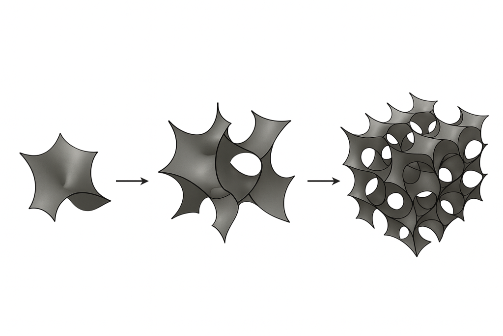
There are many types of lattice structures to choose from. To name a few: gyroid lattice, strut lattice, and planar based lattice. This project will focus on gyroid lattices. Gyroids belong to the family of triply periodic minimal surfaces (TPMS). They offer unique mechanical properties and high surface areas creating favorable thermo-mechanical properties compared to other lattice structures. A gyroid is defined by the implicit surface equation:

By connecting gyroids together in such a way we can generate lattice structures as seen below.
As mentioned previously, there are many design parameters to consider with gyroid lattice’s. The design inputs used in this project are:
- Porosity: Porosity controls how much empty space is present in the lattice cube. In this work, porosity ranges from 40% to 85%. Higher porosity generally leads to lighter structures, but also reduces stiffness and strength.
- Unit-Cell-Periods: This is the number of gyroid unit cells along each dimension of the cube, ranging from 1 to 8 periods. Visually, one can estimate the number of periods by counting the number of complete sinusoidal “waves” along a given direction.
- Grading: Grading determines how porosity varies from the bottom to the top of the cube, with values between 1.0 and 3.0. A value of 1.0 corresponds to a uniform lattice, while 3.0 indicates the top is three times more porous than the bottom. This is an important design feature for energy-absorbing applications, since the more porous regions collapse first and help dissipate mechanical energy more effectively.
The Solution: Bayesian Optimization
For this project, I developed a Bayesian optimization model to intelligently search the design space, rather than rely on random exploration or grid search. Bayesian optimization builds probabilistic surrogate model ( a Gaussian Process in this case) and uses it to decide where to sample next. The idea is to balance exploring uncertain areas of the design space, while exploiting the most promising areas of the design space.
Project Goals
- Build and end-to-end computational pipeline from geomtery generation to finite element analysis.
- Implement Bayesian optimization using Gaussian processes and intelligent acquisition functions.
- Maximize specific stiffness (stiffness per unit mass) using the BO model, finding the most efficient lattice geometry.
Learning Objectives
- Bayesian Optimization Theory
- Gaussian process for surrogate modeling
- Acquisition function (Expected Improvement)
- Exploration vs. Exploitation trade-offs
- Computational Mechanics
- Finite Element Analysis
- MOOSE framework
- Mesh convergence
- Automated Workflows
- Geometry Generation
- Mesh Generation
- Running Simulations
To learn more about each of the above objectives, click the tabs below!
Overview
Bayesian optimization is a technique that leverages the principles of Bayesian inference to find the optimal (minimum or maximum) of an objective function efficiently. These are ideal for dealing with expensive black box functions such as an expensive finite element simulation. At a high level, the Bayesian optimization algorithm is:
- Select the next sample by maximizing the the acquisition function
- Evaluate the sample (in this case by running the FEA simulation)
- Update the surrogate model
- Repeat steps 1-3 until a stopping criteria is met.

The blue line here represents the mean of the Gaussian process (the surrogate model), the dotted gray line represents the actual function, the black points are actual observed points, and the shaded blue area represent the variance, or uncertainty in the surrogate model. The black line represents the acquisition function; the function that determines the next point to sample. It becomes large in regions that either look promising according to the surrogate (high predicted value) or are still uncertain, reflecting the exploration–exploitation tradeoff: explore uncertain regions that might hide better optima, while also exploiting regions that already look good.
The Surrogate Model
The first key to the puzzle in Bayesian optimization is the Surrogate model. For expensive black box functions, we approximate the solution using a cheaper statistical model known as a surrogate model. A popular choice for the surrogate model, including the one chosen for this project is a Gaussian processes (GPs). A Gaussian process is a stochastic process that assumes any finite collection of points in the input space has a jointly Gaussian (multivariate normal) distribution. This gives us, at every x, a predicted mean (our best guess of the function value) and a variance (our uncertainty), which together define the surrogate model.
In this work the surrogate model can be assumed as:

m(x) is the mean function (the blue line in the figure), representing our best guess of the objective at each design point.
k(x,x′) is the covariance kernel, which encodes how similar two designs x and x′are and controls the smoothness and shape of the surrogate.
Acquisition Function
The second key piece in Bayesian optimization is the acquisition function. The acquisition function uses the surrogate model, which is what we know now, and tells us where to sample next. There are many acquisition functions to choose from, in this work we use the Expected Improvement (EI) acquisition function. As this is a maximization problem, the EI at a point x is the expected amount by which sampling at x will improve upon the current best observed value:

At each iteration of Bayesian optimization, we simply choose the design x that maximizes EI and run the next FEA simulation there.
Exploration vs. Exploitation Trade-Off
The exploration vs. exploitation trade-off is a central concept in Bayesian optimization. Exploitation means sampling designs that the surrogate model already predicts will perform well, refining and improving the current best solution. Exploration means sampling in regions where the surrogate is still highly uncertain, in case there are even better designs that have not yet been tested.
Expected Improvement balances these two goals automatically: it is high both where the predicted performance is strong (exploitation) and where uncertainty is large (exploration), allowing the algorithm to efficiently discover high-performing designs with relatively few expensive FEA simulations.
Finite Element Analysis
Finite element analysis (FEA) is the primary numerical method used in this project. This involved discretizing the gyroid structures and solving governing equations over this mesh using finite element solvers. FEA allows us to capture complex geometries and material behaviors and to compute quantities of interest such as effective stiffness and energy absorption. These FEA results are treated as evaluations of an expensive black-box function inside the Bayesian optimization loop.
Test Setup
The finite element simulations were performed using a small-strain, linear elastic formulation, consistent with the assumed material behavior of PLA over the strain range of interest. Small-strain kinematics are appropriate here because the deformations are relatively modest and we are primarily interested in effective stiffness rather than large-deformation or post-yield behavior. In practice, PLA is relatively brittle and will tend to crack or fail rather than undergo large elastic strains, so a small-strain, linear elastic model is a reasonable approximation for the loading levels we consider. While we did not have time this semester to perform physical testing, our goal is to validate these simulation results using 3D-printed PLA samples in future work. Although this modeling choice limits our ability to capture nonlinear effects such as energy absorption at large strains, it still provides valuable insight into the effective stiffness of the gyroid lattice designs.
With that our test setup is as follows:
Boundary Conditions: The bottom surface of the lattice was fixed, representing a rigid support. The top surface was constrained in the x and y direction at a point, and free in the z-direction, ensuring uniform compression of the lattice. This boundary condition setup simulates a uniaxial compression test between rigid platens.
Loading: A prescribed displacement of -0.025 mm in the z direction was applied to the top face. This corresponds to a 0.1% nominal strain (compression) ensuring we stay in the linear elastic regime.
Material Properties: The PLA material was modeled with a Young’s modulus of E = 3.5 GPa and Poisson’s ratio of ν = 0.36 and a density of 1.24 g/cm^3.
Output Metrics:From each simulation, we extracted the following quantities:
- Reaction force at the top surface, converted to stress using the nominal cross-sectional area
- Applied displacement, converted to nominal strain
- Elastic modulus, calculated as the slope of the stress-strain curve
- Effective density, computed from the lattice volume and PLA material density
- Specific stiffness (E/ρ), our primary optimization objective, representing stiffness per unit mass this is our objective.
MOOSE
As I said before, many commercial finite element softwares struggle to work with lattice structures. I made the decision to use MOOSE (Multiphysics Object Oriented Simulation Environment) which is a finite element framework from Idaho National Labs (INL). This software makes it easy to upload a Gmsh file and easily create an input file to run the test. Another advantage of running MOOSE is it can easily be worked into my workflow pipelines, making it possible to automatically run simulations. This was crucial both for the original data set, and running the Bayesian optimization.
A sample simulation showing the displacement and the strain in the zz direction is shown below.

Mesh Convergence
Since FEA provides an approximate numerical solution that depends on the discretization of the domain, it is essential to ensure that the chosen element size is sufficiently refined. If the mesh is too coarse, important geometric or stress features of the gyroid structure may be lost, leading to inaccurate stiffness predictions. Performing a mesh convergence study allows us to identify a mesh density at which the solution no longer changes significantly with further refinement, ensuring that the FEA results used in the surrogate model and Bayesian optimization pipeline are reliable.
A mesh convergence study is shown below. The relative change in E_eff on the graph on the left changes less than 1% in between mesh sizes, indicating the mesh is converged to a solution. An element size of 0.015625mm was selected as it provided a converged mesh at a smaller computational cost than using smaller elements.

Overview
In order to run this model, we needed to automate a couple of workflows. The first was generating a dataset. Although the dataset does not need to be very large because Bayesian optimization searches the design space efficiently, the surrogate model still requires an initial set of simulations to learn from. This requires running simulations one after the other and saving the results. A painstakingly slow process, especially without automated pipelines.
Another automated workflow is needed for running the Bayesian optimization. We want the acquisition function to automatically select the next sample point and run that simulation without human intervention. Before we can set up the end-to-end pipelines, we needed to build the individual steps of the pipelines.
Automated Geometry Generation
To automate the geometry generation, a Python script was made that creates an STL file of the desired gyroid lattice. The script takes three input parameters and produces an STL with the corresponding properties. The cube size is fixed at 25 mm in the script to align with the test setup used in MOOSE.
Automated Mesh Generation
Once the STL is generated, it must be discretized into a finite element mesh. However, meshing such complex gyroid geometries is not straightforward, and many automatic mesh generators in commercial software struggle or fail on these types of structures.
Instead I used Gmsh, an open-source three-dimensional finite element mesh generator. Gmsh can be driven through a python script to take an stl and turn it into a .msh file using tetrahedral elements. This script took the name of the file and a desired element size and created a mesh. These mesh’s are now ready to be handed into MOOSE for finite element analysis.
Complete Workflows
The first step is too create the dataset. To do this I combined the first two steps, and the MOOSE simulation into a single pipeline. I then utilized Latin Hypercube sampling to generate the inputs for the gyroid lattice’s. This ensured we had good coverage of the design space. I then ran it 400 times to generate 261 usable samples. Some of the inputs created invalid geometries and could not be meshed. In total this took four days to complete and the process can be visualized below.

Once the dataset was complete, the Bayesian optimization model was ready to be run. Now instead of using Latin Hypercube sampling to generate the inputs, they are generated using the acquisition function. Bad geometries were penalized so the acquisition function knew to stay away from them. The process for this workflow is visualized below.

The Github repo for this project can be found here here
About the Author

Hi, my name is Ryan Lutz, and I’m a second-year Master’s student in Mechanical Engineering at Duke University, expecting to graduate in May 2026. My research sits at the intersection of computational mechanics, optimization theory, and machine learning. I earned my B.S. in Civil Engineering from Clemson University before pivoting to mechanical engineering at Duke.
This project is my master’s capstone, motivated by the growing use of lattice structures, particularly gyroid lattices, in aerospace applications. After reading extensively about their mechanical performance and design challenges, I felt there had to be a faster, more systematic way to obtain optimal lattice designs. Leveraging my background in optimization and machine learning, this project was born as an attempt to make that design process both smarter and more efficient.
Other Research
My thesis research focuses on contact mechanics, where I am developing a novel 2D smoothed mortar contact formulation in collaboration with Lawrence Livermore National Laboratory (LLNL). The goal is to create a robust, smooth formulation that can be seamlessly integrated into global optimization frameworks. Beyond this, I work in Dr. John Dolbow’s research group at Duke, where we focus on problems in fracture mechanics and related topics in computational solid mechanics.
If you’d like to hear more about my work or are interested in connecting please don’t hesitate to reach out!
References
[1] N. Khan and A. Riccio, “A systematic review of design for additive manufacturing of aerospace lattice structures: Current trends and future directions,” Progress in Aerospace Sciences, vol. 149, 101021, 2024
[2] F. Günther, S. Pilz, F. Hirsch, M. Wagner, M. Kästner, A. Gebert, M. Zimmermann, “Shape optimization of additively manufactured lattices based on triply periodic minimal surfaces,” Additive Manufacturing, vol. 73, 103713, 2023.
[3] M. Kashfi, S.H. Nourbakhsh, A. Amiripour, H.J. Lim, “Constrained functionally graded gyroid structure for tunable energy absorption,” Materials & Design, vol. 258, 114693, 2025.
[4] J. Peloquin, Y. Han, K. Gall, “Printability and mechanical behavior as a function of base material, structure, and a wide range of porosities for polymer lattice structures fabricated by vat-based 3D printing,” Additive Manufacturing, vol. 78, 103892, 2023.
[5] M. J. Uddin, J. Fan, “Machine learning framework to predict the mechanical properties of photopolymer gyroid lattices at various strain rates,” Polymer Testing, vol. 151, 108971, 2025.
[6] Introduction to Bayesian Optimization. Ax Documentation, Meta Platforms, Inc. Available at: https://ax.dev/docs/intro-to-bo/
[7] Peng, X., Huang, Q., Zhang, Y., Zhang, X., Shen, T., Shu, H., & Jin, Z. (2021). Elastic response of anisotropic Gyroid cellular structures under compression: Parametric analysis. Materials & Design, 205, 109706. https://doi.org/10.1016/j.matdes.2021.109706
[8] Zhang, Y., Xue, Z., Chen, L., & Fang, D. (2009). Deformation and failure mechanisms of lattice cylindrical shells under axial loading. International Journal of Mechanical Sciences, 51(3), 213–221. https://doi.org/10.1016/j.ijmecsci.2009.01.006
[9] Zhang, C., Zheng, H., Yang, L., Li, Y., Jin, J., Cao, W., Yan, C., & Shi, Y. (2022). Mechanical responses of sheet-based gyroid-type triply periodic minimal surface lattice structures fabricated using selective laser melting. Materials & Design, 214, 110407. https://doi.org/10.1016/j.matdes.2022.110407
[10] Senhora, F. V., Chi, H., Zhang, Y., Mirabella, L., Tang, T. L. E., & Paulino, G. H. (2022). Machine learning for topology optimization: Physics-based learning through an independent training strategy. Computer Methods in Applied Mechanics and Engineering, 398, 115116. https://doi.org/10.1016/j.cma.2022.115116
[11] Chi, H., Zhang, Y., Tang, T. L. E., Mirabella, L., Dalloro, L., Song, L., & Paulino, G. H. (2021). Universal machine learning for topology optimization. Computer Methods in Applied Mechanics and Engineering, 375, 112739. https://doi.org/10.1016/j.cma.2019.112739
[12] Ruiz de Galarreta, S., Jeffers, J. R. T., & Ghouse, S. (2020). A validated finite element analysis procedure for porous structures. Materials & Design, 189, 108546. https://doi.org/10.1016/j.matdes.2020.108546
[13] Khaderi, S. N., Deshpande, V. S., & Fleck, N. A. (2014). The stiffness and strength of the gyroid lattice. International Journal of Solids and Structures, 51(23–24), 3866–3877. https://doi.org/10.1016/j.ijsolstr.2014.06.024