Setting Up Dabble to Control the Moveo via Mobile Phone
This tutorial will cover how to use Dabble to control a single stepper motor. This can be further implemented to control all motors on the BCN 3D Moveo, providing greater degrees of freedom to its movement.
Prerequisites:
- Install Arduino IDE
- HC-O5 bluetooth module
- Arduino Mega or Arduino Mega Clone
- Apple or Android Device
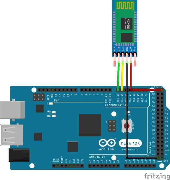
The following wiring diagram, copied to Figure 1, provided by Stempedia details how the Bluetooth module should be connected. This tutorial uses the HC-05, which is described as “a Serial Port Protocol Bluetooth working on Bluetooth protocol ‘Bluetooth V2.0+EDR’,” according to STEMPedia [4].
GND of HC-05 to GND of Arduino Mega
VCC of HC-05 to 5V of Arduino Mega
RX of HC-05 to Pin 14 of Arduino Mega
TX of HC-05 to Pin 15 of Arduino Mega
You may want to change the name of your HC-05 BLE device. If so, follow this tutorial Viral Science [5].

Figure 1: Fritzing diagram for connection from HC-05 BLE to Arduino Mega. Courtesy of STEMPedia.
As an exercise for the reader, consider the following questions:
- Bluetooth protocol and interrupting commands?
- How to print position feedback to a screen (LCD, Serial Monitor, etc.) without interrupting the commands?
Next, write some code to turn one of the motors. Follow the wiring diagram in Figure 2. Reference this tutorial by Maker Guides as well, if necessary, when wiring the DRV8825 [3].
Right Power Rail – 24 Volt
Left Power Rail – 5 Volt
NOTE: You may want to add a 100 microFarad Capacitor to the 24 Volt Power rail to protect the board against voltage spikes.
For wiring the DRV8825:
*Down the right side of the board*
VMOT – 24 Volt
GND – Ground
A1, A2, B1, B2 – Motor Coils
GND – Ground
*Down the left side of the board*
MS0 – Pin 13
MS1 – Pin 12
MS2 – Pin 11
Reset – 5 Volt
Sleep – 5 Volt
Step – Pin 10
Dir – Pin 9

Figure 2: Fritzing diagram for connection from DRV8825 to Arduino Mega.
Now, write a simple script to turn the motor clockwise and counter clockwise. More sample code is available via this tutorial from Last-Minute Engineers [1].
First, add the following headers and include the Dabble library. Download the library from Arduino include the Dabble library, if not already installed [2].

Figure 3: Initializing the Arduino script.
Now, set up the step and direction pins as in Figure 4. From the Fritzing diagram, the step pin is connected to pin 9 of the Arduino microcontroller and the direction pin is connected to pin 10.

Figure 4: Defining the pins.
Now, in “void setup()” function, set the step and direction pins to be output pins. To enable a Bluetooth connection, use Dabble.begin(9600), as seen in Figure 5. The 9600 is the baud rate of the HC-05 BLE module. Read more about baud rates and serial connection from Sparkfun [6].

Figure 5: Adding the Dabble.begin(9600) function.
Now, every time the process loops, it must process any incoming commands using the Dabble.processInput() command. To check if a button is pressed, use a simple “If” statement.
Set the direction high using the digitalWrite command, like in Figure 6. To step the motor, set the step pin high, wait 10 milliseconds, set it low, and wait 10 more milliseconds.

Figure 6: Processing incoming commands.
Repeat the same statement but for a different button. For example, the circle button is used in Figure 7. Now, upload the script to the board.

Figure 7: Defining a process for when the circle button is pressed.
Now, open the Dabble app on an Apple or Android device. The interface is pictured in Figure 8. Click the plug-shaped icon in the upper right and search for the HC-05 BLE device.

Figure 8: The Dabble mobile interface.
References
[1] Control Stepper Motor with DRV8825 Driver Module & Arduino. Last Minute Engineers. https://lastminuteengineers.com/drv8825-stepper-motor-driver-arduino-tutorial/
[2] Dabble. Arduino. https://www.arduino.cc/reference/en/libraries/dabble/
[3] De Bakker, Benne (2019). How to control a stepper motor with DRV8825 driver and Arduino. Maker Guides. https://www.makerguides.com/drv8825-stepper-motor-driver-arduino-tutorial/
[4] Getting Started with Dabble. STEMPedia. https://thestempedia.com/docs/dabble/getting-started-with-dabble/
[5] HC-05 Bluetooth Module | Change Name and Password | AT Commands. Viral Science – The Home of Creativity. https://youtu.be/DgFZE16UKTM
[6] Jimblom. Serial Connection. Sparkfun. https://learn.sparkfun.com/tutorials/serial-communication/rules-of-serial
© 2025 Duke MEMS: Experiment Design and Research Methods
Theme by Anders Noren — Up ↑
