
Abstract
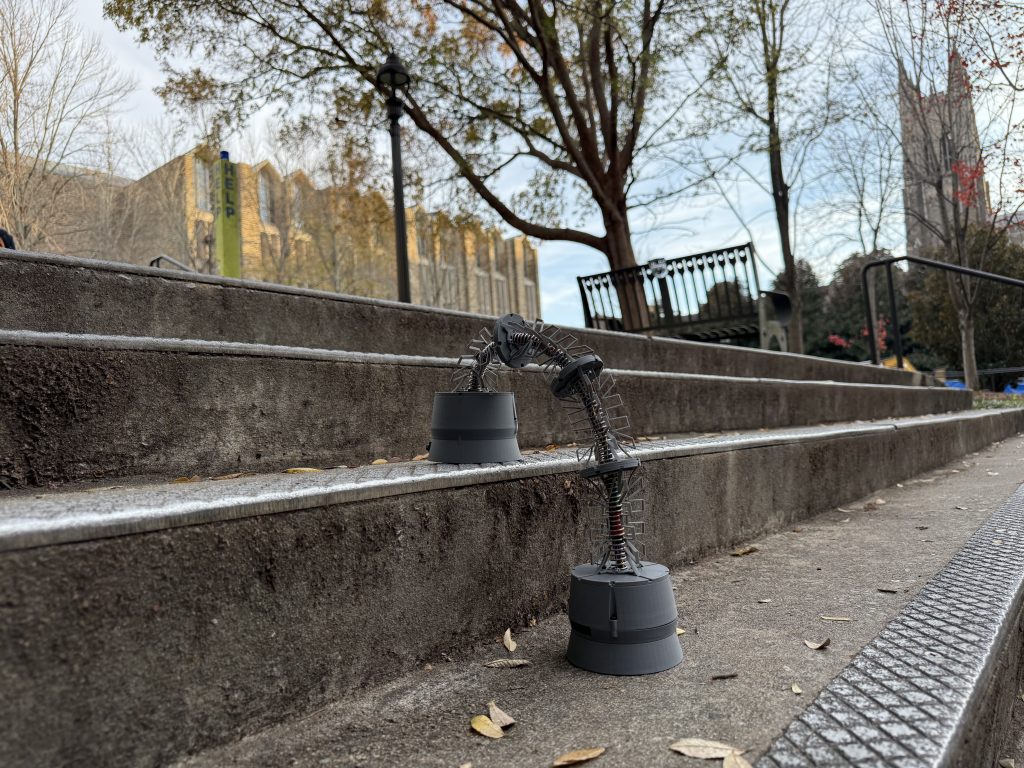
This work introduces hydra, a slinky-inspired tendon-driven continuum robot (TDCR). Built from modular units that bend and flex through tendon actuation, the robot produces wave-like motion for locomotion. Each unit is lightweight, compact, and designed for easy connection, making the system highly adaptable in both length and configuration. The robot’s feet house the motors, electronics, and batteries required for untethered operation, enabling wireless teleoperation. While tendon-driven continuum robots have been widely studied for manipulation, their use in generating locomotion remains largely unexplored. By applying tendon actuation to achieve slinky-like movement, hydra demonstrates a novel approach to mobile continuum robotics. This platform provides opportunities to investigate new forms of distributed actuation and bio-inspired locomotion, with potential applications in search-and-rescue, confined-space inspection, and soft robotics research.
Background
Current tendon driven robotic systems [1], such as continuum arms and snake-like robots, demonstrate high dexterity in manipulation and navigation but are limited in their modes of locomotion. Most existing designs emphasize serpentine crawling, sidewinding, or precise bending for manipulation tasks, yet few explore dynamic, cyclic locomotion strategies akin to a slinky’s expansion–contraction and tumbling motion. This represents a missed opportunity: slinky-like mobility offers unique advantages for traversing irregular terrains, scaling vertical structures, and adapting to constrained environments where wheels, tracks, or traditional gaits are ineffective.

Goals
The primary goal of this project is to demonstrate the feasibility of tendon-driven, slinky-like locomotion as a novel approach to continuum robot movement. By combining antagonistic tendon actuation with a modular and compliant backbone structure, this project aims to achieve motion that preserves the adaptability and and dexterity of traditional tendon-driven continuum robots, while introducing efficient and scalable locomotion capabilities.
The scope of this work focuses on achieving basic locomotion through teleoperation, allowing direct control of the robot’s motion via user keystroke input. While current efforts emphasize validating the mechanical and control principles behind this motion, future iterations could expand into autonomous behaviors using feedback from the integrated sensor encoders and onboard IMU for closed-loop control.
Problem Statement
A mobile tendon driven robot that replicates slinky dynamics would combine compliant, continuum-inspired mechanics with dynamic mobility to achieve a robust and adaptable locomotion plan. The novelty of translating tendon-driven continuum actuation into slinky-inspired locomotion paired with modular unit design, offers a new paradigm for adaptive, terrain-agnostic mobility in robotics.
Educational Problem
Considering the small scale of the project, the cost to develop and prototype this robot is relatively cheap. The most expensive parts come from the embedded hardware, such as the microcontroller and motors which are easily accessible from popular vendors such as Amazon and DigiKey. The components of this small robot do not require regular maintenance. The physical structure of the robot is comprised entirely of 3D printed parts, which can be sourced from 3D printers on campus available to students.
In addition to this capstone course, developing the robot requires knowledge of control systems, programming, and mechanical design, all of which are part of a standard mechanical engineering curriculum at accredited universities. To allow others to replicate and conduct their own experiments on this robust hardware platform, this project is open-sourced on a dedicated GitHub repository.
Research Problem
Due to the narrow scope of our project this semester, this project is limited to a demonstration of the feasibility of a mobile, untethered TDCR. Our work is interesting in that it provides a robotic platform to experiment with different types of locomotion and adaptation. Tendon-driven robots are known for being flexible, lightweight, and adaptable, making them ideal for complex tasks that require precision and accuracy.
Additional work into refining simulation, machine learning algorithms, and terrain-informed locomotion would advance this project into conference caliber research.

Design Methodology
The design is decomposed into three main subsystems: hardware, electronics, and software.
Summary
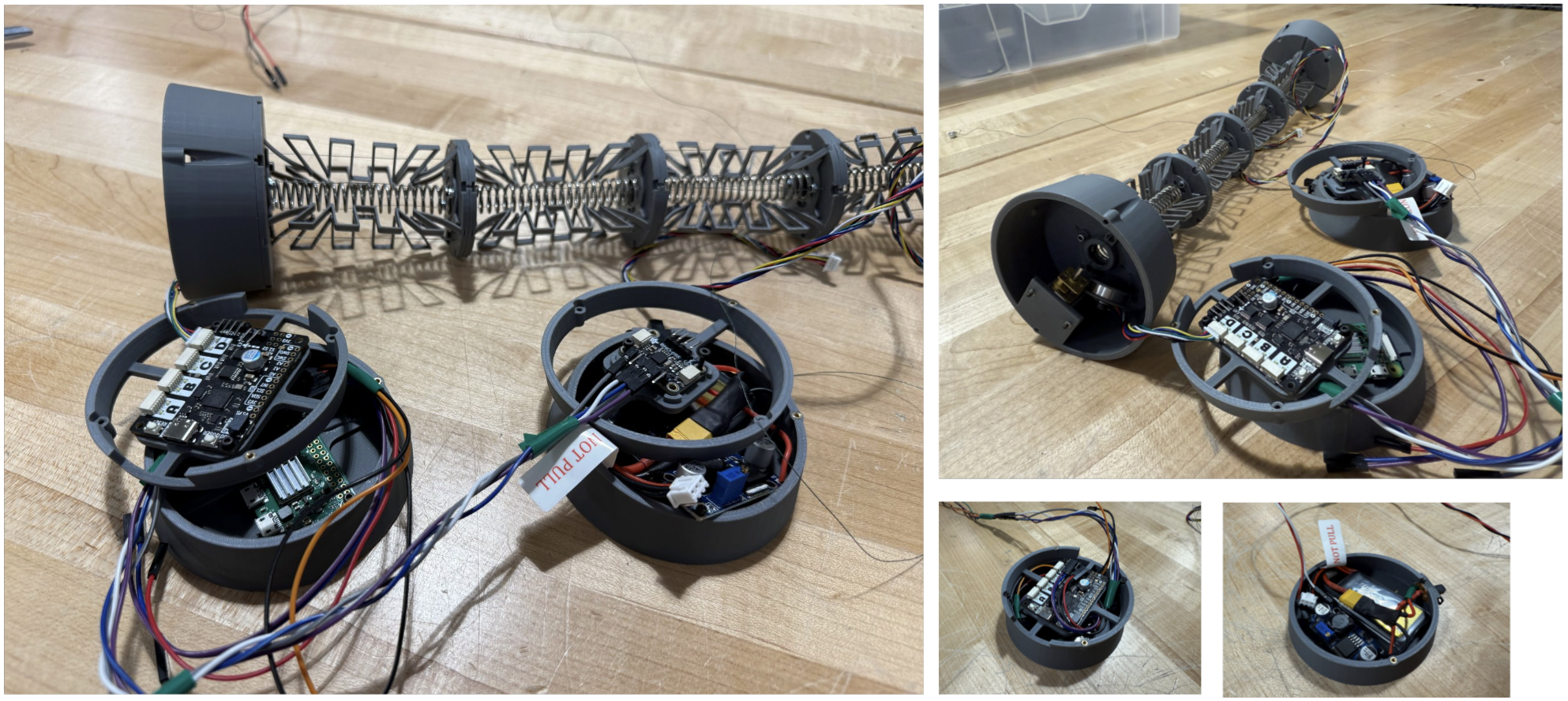
The hardware design of hydra includes both the mechanical structure and the integrated electronics housing. The robot’s body is formed using spacer discs, connectors, and support wings that align and constrain the tendon routing while maintaining structural flexibility. The end effectors serve a dual purpose: they act as the robot’s “feet” for locomotion and also contain the electronics and wiring. All components were modeled in SolidWorks and manufactured using 3D-printed parts. The module unit design is adapted from a research paper by the Continuum Robotics Laboratory at University of Toronto [3].
Spacer Discs and Connectors
Our spacer disk design was inspired by a tendon-driven robot developed by the Continuum Robotics Laboratory, which uses a lightweight modular segment architecture with pre-programmable stiffness. The spacer discs divide the robot into individual segments, each with its own bending behavior and flexibility. We adapted this concept for hydra by scaling the discs to a 10 mm outer diameter, ensuring sufficient space for tendon routing while maintaining structural stability. The connectors are integrated with the spacer discs to secure the support wings and maintain alignment throughout the structure.

Support Wings
The support wings were also based on the Continuum Robotics Laboratory robot [2], which uses angled wings to provide structural support while allowing a spring-like flex during bending. Given the mobile nature of our robot, we needed to increase the flexibility of the support wings to allow for a sufficient bending range. To achieve this, we modified the initial design by increasing the wing length, which required adjusting the fundamental wing geometry. These changes improved the overall bendability of each segment while maintaining structural support.


Module Unit Assembly
Each module unit assembly consists of two spacer discs, two connectors, and four support wings. These assemblies form the individual bending segments of the robot’s structure. The following diagram illustrates the progression of our module unit designs over time.

End Effectors
Our end effectors function both as the robot’s method of locomotion and as the housing for the electronics. We designed them to be as compact as possible while still providing sufficient internal space for all components. The end effectors are divided into three stacked layers, each connected using counterbored fasteners to securely enclose and organize the electronics. The following diagram shows the progression of our foot unit designs over time.

Electronics Housing
The internal structure of the end effectors serves as the housing for all electronic components. We mounted each component to its designated layer with snug fits and screws to keep everything firmly in place during motion and transportation.
Full Robot Subassembly
The final subassembly (v6) of all the hardware components, with a description of the electronics housing, is shown below.

Full Robot Assembly
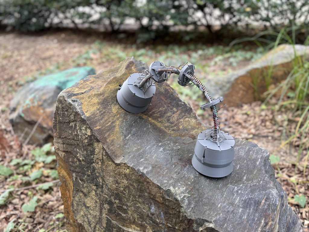
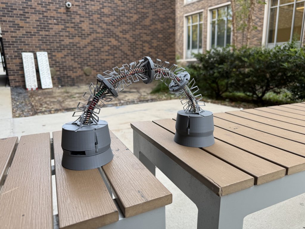
Using four connected module units, two end effectors, and a compression spring as the backbone, our full robot assembly is shown below.

Summary
The primary goals of the electronics subsystem were to:
- coordinate multi-motor tendon actuation,
- provide reliable feedback for closed-loop control, and
- interface cleanly with the hardware and software subsystems.
When selecting components, we prioritized low weight, low power consumption, and compact form factor, since the robot’s locomotion depends on keeping mass centered and minimizing inertial resistance. We also needed electronics capable of precise actuation, real-time sensing, and robust communication between control layers. Each component was chosen to balance performance with simplicity, enabling rapid integration.
The chosen components form an electronics subsystem that is tightly integrated with the robot’s hardware and software: the hardware provides the physical structure and tendon mechanics that the electronics drive, and the software translates sensing and control algorithms into precise electrical commands. The electronics act as the bridge between the two, converting high-level behavior into motor actuation, collecting real-time sensor feedback, and ensuring the mechanical system responds predictably to the software’s instructions. This seamless interaction allows the robot to behave as a cohesive system and to execute coordinated, controlled movements in an efficient and reliable manner.
Computer - Raspberry Pi Zero 2 W
The Raspberry Pi Zero 2 W serves as the onboard computer responsible for all high-level control and decision-making. The Pi runs the robot’s locomotion algorithms, gait scheduling software, and the teleoperation modules. It also interfaces with sensors (i.e., IMU) to interpret robot state and environmental cues. The Pi sends target motor commands to the motor controller and receives diagnostic feedback. Its compact form factor and integrated wireless networking make it well-suited for a lightweight, modular robot like hydra.
Motor Controller - Pimoroni Motor 2040
The Pimoroni Motor 2040 is the real-time actuation backbone of the electronics system. Powered by the RP2040 microcontroller, it provides four motor driver channels and eight quadrature encoder inputs, enabling precise closed-loop control of hydra’s tendon-driven motors. The board handles time-critical tasks such as PWM generation, encoder counting, current sensing, and PID control, functions that would otherwise burden the Pi Zero and reduce reliability. The Motor 2040 communicates bidirectionally with the Raspberry Pi, converting high-level actuation goals into low-level torque or speed commands and returning motor state information for monitoring and control.
Motors - Pololu N20 Gearmotors (210:1) with Magnetic Encoders
Each Pololu N20 motor functions as a compact, high-torque actuator capable of pulling tendon lines to deform or compress robot segments. The 210:1 gearbox increases available torque, allowing the robot to generate the forces needed for hydra-like contractions and slinky-style flipping maneuvers, whilst maintaining the precise control needed for the project. The magnetic encoders integrated into each motor provide high-resolution position feedback via quadrature signals. This enables accurate tendon displacement measurement, which is essential for closed-loop segment control, synchronized multi-motor actuation, and repeatable locomotion behaviors
IMU - Adafruit BNO055
The Adafruit BNO055 is a 9-DOF inertial measurement unit that performs onboard sensor fusion to output stable orientation estimates (Euler angles or quaternions). This sensor provides hydra with a continuous understanding of its orientation in three-dimensional space. The IMU is critical for detecting flips, monitoring stability, and evaluating the effectiveness of dynamic maneuvers. By offloading fusion calculations internally, the BNO055 reduces computational load on the Pi Zero and ensures consistent orientation data even under rapid motion.
Battery - Tattu 2S 7.4 V LiPo Battery
The Tattu 2S 7.4 V LiPo battery supplies power for the entire electronic system, providing the necessary voltage and discharge capacity to drive multiple motors while also powering the Raspberry Pi and IMU. LiPo batteries are well-suited for mobile robots due to their high energy density and ability to deliver high instantaneous current. The chosen battery balances runtime, power delivery, and weight, supporting hydra’s dynamic locomotion without exceeding mass constraints or compromising mobility.
Voltage Regulation - LM2596 Buck Converter
The LM2596 buck converter is used to regulate the robot’s battery voltage and provide a stable, lower-voltage supply to sensitive electronics. Because the Tattu 2S LiPo battery outputs ~7.4V, this voltage must be stepped down before powering components such as the Raspberry Pi Zero W, the motor controller’s logic circuitry, and the IMU. The LM2596 provides an efficient DC-DC conversion with sufficient current capacity for our system, ensuring that voltage remains within safe operating limits even during high-load events such as rapid motor actuation. By isolating the computation and sensing electronics from battery fluctuations and motor-induced noise, the buck converter improves system reliability and protects downstream components from damage.
Circuit Diagram

Summary
The software for hydra consists of two primary scripts that allow for the communication of data across the Raspberry Pi Zero 2 W and the Pimoroni Motor 2040. The Raspberry Pi is responsible for dealing with high level commands, calculation, and intaking sensor data to. To directly control hydra, a user would wirelessly SSH into the Raspberry Pi, taking advantage of its network capabilities. The Pimoroni motor controller is able to receive motor commands from the Raspberry Pi via serial communication and perform low level closed loop control to ensure the Pololu N20 motors actuate with sufficient accuracy for locomotion.
Software development for hydra initially began by testing the functionally of the key electronic components for hydra. Once initial tests proved feasibility, the functionality of the software was improved and expanded upon. This process involved a fair amount of iteration of troubleshooting to reach the current capabilities hydra now possess, such as teleoperation.
Pimoroni Motor Controller Script
The motor controller utilizes CircuitPython as its primary coding language. This allows for the Pimoroni to easily interface with the Python scripts run on the Raspberry Pi while maintaining a small file size. Originally software development for the Pimoroni motor controller began as means by which to test the functionality of the key electronics components for hydra. This was accomplishable thanks to a number of examples scripts provided by Pimoroni. An early issue regarding the configuration of the Pololu motor cables was thought to be a software issues at first, which caused several early delays in development for the project.
With the functionality of the Pololu motors and encoders confirmed, a starter script with a PD position controller was upgraded to allow for setpoints to be sent via serial communication. A laptop was used to manually send these serial commands to the Pimoromi via the USB-C port. With basic serial communication confirmed, the use of a laptop was replaced with a automatic script on the Raspberry Pi. To reduce the size needed for wiring in the electronics housing of the Pimoroni, the USB-C port was abandoned in favor of the TX/RX pins on both serial devices. While this did remove the bulky form factor of the USB-C cable, it resulted in several timing issues for serial communication between both devices. By implementing a more robust and defined startup sequence for the communication channel between the Raspberry Pi and Pimoroni, these issues were solved.
With serial communication capable of reliably sending position commands, several other new commands with added functionality were introduced. These included: a status command which would relay the current position of all motors, a reset command which would effectively reset the software of the board, and an exit command which would zero all motors, stop communication, and quit the script.
Motor Position Control Script
- SET_POS 1 90 → sets Motor 1 position to 90°
- SET_POS 2 -45 → sets Motor 2 position to −45°
- STATUS → queries both motors for position
- RESET → reinitializes board (soft restart)
- EXIT → drives both motors to zero and quits
Motor Teleoperation Script
- Motor 1:
- a = small CW step
- A = Large CW step
- d = small CCW step
- D = Large CCW step
- Motor 2:
- s = small CW step
- S = Large CW step
- w = small CCW step
- W = Large CCW step
- z or Z -> Status
- r or R-> Reset
- x or X -> Exit (drive to 0°, then quits)
Experimental Methods
To evaluate the performance and reliability of hydra, we will outline a comprehensive testing methodology divided into three categories: robustness, trajectory tracking, and locomotion. These tests are designed to validate structural durability, motion accuracy, scalability, and adaptability across various environments.
Objective: Assess the robot’s ability to withstand added loads during locomotion while maintaining structural integrity and function.
| Criterion | Description | Target Value |
|---|---|---|
| Structural Load Capacity | Robot must support half its total weight without structural failure | ≥ 250 g |
| Weight | Robot must remain lightweight to reduce torque and actuation demand | ≤ 1 kg |
| Scalability | Performance must remain nominal when robot size increases | Up to 8 units |
We define robustness as the ability of our robot to support added load while performing locomotion.
To test the durability of our structure, we model the robot as a cantilever beam with one end fixed on a vertical surface and the other end free. The free end contains ballast equal to half the weight of the robot, which is approximately 250 g. We measure the deflection of the free end and identify the critical stress points where the robot has the greatest deformations.
The total weight of the robot should be less than 1 kg. A lighter robot requires less torque and has a lower actuation demand, which allows the robot to scale to more module units.
The baseline configuration uses 4 module units. To evaluate scalability, we increase the robot’s length up to 8 units (2x the nominal size), which allows us to assess how performance changes with increased structural complexity.
Objective: Evaluate the robot’s accuracy and precision in reaching static poses and following dynamic paths.
| Criterion | Description | Target Value |
|---|---|---|
| Accuracy | Robot must reach static and dynamic target poses with minimal error | ≥ 90% success rate |
| Precision | Tip/path variation between trials must remain small | ≤ 2 cm |
| Adaptability | Must maintain functional tracking across multiple terrains | ≥ 3 terrains |
We define trajectory tracking as the robot’s ability to accurately and consistently reach commanded poses or follow prescribed motion paths.
To evaluate this behavior, we use the baseline configuration of 4 modules and test the robot under both static and dynamic conditions. For static tracking, the robot is commanded to emulate five distinct poses, and we measure accuracy by recording the foot displacement (mm) from each target. For dynamic tracking, the robot tip follows a straight-line path, and accuracy is assessed by measuring the lateral drift (mm) of the outstretched tip during motion. Precision is quantified by calculating the average deviation (mm) among repeated paths for both static and dynamic trials.
To test adaptability, we evaluate the robot on concrete (flat surface), a vertical wall (90° incline), and dirt (uneven surface) on the same performance metrics above to ensure reliable tracking across varied terrain conditions.
Objective: Evaluate locomotion and trajectory metrics across repeated gait cycles and varied environments.
| Criterion | Description | Target Value |
|---|---|---|
| Speed | Robot must traverse efficiently over ground or incline | ≥ 0.15 m/s |
| Accuracy | Robot must maintain acceptable lateral drift when following a path | ≥ 90% success rate |
| Precision | Step placement must not deviate significantly during gait cycles | ≤ 2 cm |
| Adaptability | Must traverse and recover successfully on varied terrains | ≥ 3 terrains |
We define locomotion as the robot’s ability to move efficiently and reliably along a prescribed path while maintaining consistent step placement and directional stability.
To evaluate this behavior, we use the baseline configuration of 4 modules and command the robot to traverse a 1 meter straight line for 10 gait cycles, repeating the trial five times. Accuracy is assessed by measuring the lateral drift (mm) from the target line at the end of each traversal, while precision is evaluated by recording the deviation (mm) of individual steps from a designated footprint. Speed is measured by calculating the distance traveled over elapsed time, from the anchor foot at the start to the farthest foot at the end.
To test adaptability, we conduct trials on concrete (flat surface), a vertical wall (90° incline), and dirt (uneven surface) to ensure robust locomotion performance across diverse terrain conditions.
Final Result
This project served as an exploratory investigation into the feasibility of a mobile, tendon-driven continuum robot capable of slinky-like locomotion. We successfully designed and constructed a hydra-inspired TDCR with integrated sensors and wireless communication, demonstrating that untethered, slinky-style movement is achievable and establishing a foundation for future refinement and expanded capabilities.
Refer to our dedicated GitHub repository to see the more details on hydra.
Meet the Team


References
[1] M. P. Huertas Niño, M. Boutayeb, and D. Martinez, “A hybrid tendon-driven continuum robot that avoids torsion under external load,” Frontiers in Robotics and AI, vol. 12, May 2025, doi: 10.3389/frobt.2025.1576209.
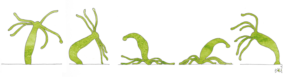
[2] Anandakuttan, Krista. “Immortal Somersaulting Hydra.” Krista Anandakuttan, 18 May 2013, https://illustratescience.wordpress.com/2013/05/17/immortal-somersaulting-hydra/.
[3] P. T. Dewi, P. Rao and J. Burgner-Kahrs, “A Lightweight Modular Segment Design for Tendon-Driven Continuum Robots with Pre-Programmable Stiffness,” 2024 IEEE 7th International Conference on Soft Robotics (RoboSoft), San Diego, CA, USA, 2024, pp. 531-536, doi: 10.1109/RoboSoft60065.2024.10522016.
[4] F. Qin et al., “Design and experiments of snake robots with docking function,” in Proc. 2022 IEEE/RSJ Int. Conf. Intelligent Robots and Systems (IROS), Kyoto, Japan, 2022, pp. 1208–1214, doi: 10.1109/IROS47612.2022.9981896.
[5] K. Zhang, J. Wang, H. Zhang, J. Jiang, X. Dou, and W. Zhao, “Cable: Design of a transmission-type snake rescue robot,” in Proc. 2024 Int. Symp. Intelligent Robotics and Systems (ISoIRS), Changsha, China, 2024, pp. 113–117, doi: 10.1109/ISoIRS63136.2024.00029.
[6] P. T. Dewi, C. Pogue, and J. Burgner-Kahrs, “Parametric design of a tendon-driven continuum robot for industrial applications,” in Proc. 2025 IEEE 8th Int. Conf. Soft Robotics (RoboSoft), Lausanne, Switzerland, 2025, pp. 1–7, doi: 10.1109/RoboSoft63089.2025.11020926.
[7] J. Zhang, H. Chen, Y. Li, X. Chu, X. Zhou, and A. Song, “Design of a bio-inspired stiffness controllable continuum robot for object grasping and moving,” IEEE Robotics and Automation Letters, vol. 10, no. 3, pp. 2982–2989, Mar. 2025, doi: 10.1109/LRA.2025.3537871.
[8] N. Zhao et al., “Modular snake-like robot designed for on-site reconfiguration in space exploration,” Biomimetics, vol. 10, no. 5, p. 293, 2025, doi: 10.3390/biomimetics10050293.
[9] Y. Zhang, Y. Yang, Z. Hu, Z. Wang, Q. Zheng, and C. Fan, “Design and optimization of a connecting joint for underwater autonomous docking and separation,” Journal of Marine Science and Engineering, vol. 13, no. 9, p. 1604, 2025, doi: 10.3390/jmse13091604.
[10] C. Qiu, Z. Wu, J. Wang, M. Tan, and J. Yu, “Locomotion optimization of a tendon-driven robotic fish with variable passive tail fin,” IEEE Transactions on Industrial Electronics, vol. 70, no. 5, pp. 4983–4992, May 2023, doi: 10.1109/TIE.2022.3189093.
[11] Q. Shao et al., “Untethered robotic millipede driven by low-pressure microfluidic actuators for multi-terrain exploration,” IEEE Robotics and Automation Letters, vol. 7, no. 4, pp. 12142–12149, Oct. 2022, doi: 10.1109/LRA.2022.3213137.
[12] S. Lilge and J. Burgner-Kahrs, “Kinetostatic modeling of tendon-driven parallel continuum robots,” IEEE Transactions on Robotics, vol. 39, no. 2, pp. 1563–1579, Apr. 2023, doi: 10.1109/TRO.2022.3226157.
[13] Y. Sun et al., “Salamanderbot: A soft-rigid composite continuum mobile robot to traverse complex environments,” in Proc. 2020 IEEE Int. Conf. Robotics and Automation (ICRA), Paris, France, 2020, pp. 2953–2959, doi: 10.1109/ICRA40945.2020.9196790.
[14] Y. Cai et al., “Modular self-reconfigurable continuum robot for general purpose loco-manipulation,” IEEE Robotics and Automation Letters, vol. 10, no. 2, pp. 1976–1983, Feb. 2025, doi: 10.1109/LRA.2025.3526560.
© 2026 Duke MEMS: Experiment Design and Research Methods
Theme by Anders Noren — Up ↑