Water Tunnels are very common in the navy and are used to test ships, weapons, etc. However, the standard build of a water tunnel resembles a rectangular skeleton made of tubes with a small see-through enclosure where we place an object. An image is provided below. This particular mini tunnel was build by students at The Citadel, Charleston, SC under the supervision of Dr. Nathan Washuta and Dr. Jason Howison.
-
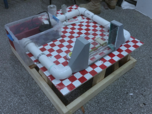
- Experimental setup led by Dr. Telenko
One of the primary requirements of the project we choose to pursue is that our project be portable as well as smaller than the one shown above. Thus, using this setup as a starting point, a needs assessment was carried out. The primary needs of the new experimental setup are:
- Transparent outer enclosure help see through the glass and assess the flow.
- Rheoscopic particles in the fluid help to observe the effect of the wing geometry on the flow.
- As water tight as possible to ensure minimal error in flow rate measurement.
- A known volumetric flow rate and inlet area so as to measure velocity.
- A platform on which we can place the airfoil at a known angle of attack.
This project aims to break down the basics of aerodynamics. In this field, it is first necessary to understand the basics of fluid statics and dynamics so that we may then use the concepts we learn by adding specifications to account for only a particular fluid of our choice.
One of the most common testing methods in the field of Flow Vizualization is a water tunnel. These tunnels are helpful because it allows us to spatially scale down a wind tunnel while still testing in a flow regime that is valid. Its applications
Through the means of this project and website, I hope to break down the concepts of Lift, Drag and other aerodynamics concepts. I also hope to set the stage for a future project that increases overall complexity and applicability.
-
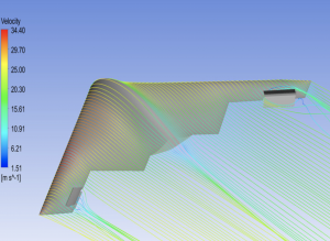
- Abstract representation of a CFD Simulation
This project and website address the visualization of the following concepts:
- Boundary Layer Separation
- Lift and Drag
Another important objective is to help set the stage for students to expand their knowledge and skillset
- D’Alembert’s Paradox
- Thin Airfoil Theory
- The Cambered Airfoil Equation
Given below is an image explaining the geometry of an airfoil. Some important terms to visualize are chord length, camber and the edges. Airfoils are most commonly named by the 4 digit NACA Nomenclature system. The first number define the percentage max camber in terms of the chord length. The next digit represents the position of this max camber from the leading edge. The last two digits define the percentage max thickness of the airfoil in terms of its chord length. If an airfoil starts off with a 00–, it is said to be symmetric along the chord.
-
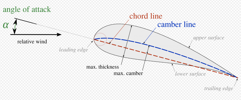
- Airfoil Geometry
In flow mechanics, a boundary layer is defined as a relatively stationary part of the fluid that immediately surrounds the object in question. As far as this project is concerned, we are mainly concerned with momentum boundary layers. The theoretical limit of the boundary layer is considered to be up to the point at which the fluid velocity equals 0.99 times the free stream velocity.
-
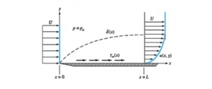
- A visual depiction of a momentum boundary layer
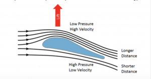
Consider an airfoil in a free stream, the velocity of which is known. We can see from the image below that there is a change in direction of flow of the air before and after interacting with the airfoil. Thus, there us a change in momentum. Newton’s second law thus requires the presence of this force to justify this change in momentum. Since the air is deflected downward, this force must be pointed upwards. This upward force is call lift.
-
- Visual Representation of Lift Generation
Drag exists due to relative motion between the fluid and the object and opposes the motion of the object. If there is no relative motion, there is no drag.
D’Alembert’s Paradox says that for incompressible inviscid flow, if we have a body moving with constant velocity, it experiences no drag. The main reason this happens is due to the assumption that the fluid is not viscous. It completely eliminates the presence of a viscous boundary layer.
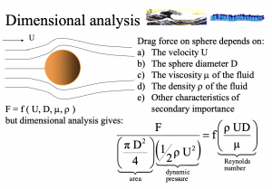
Buckingham Pi Theorem is a method of dimensional analysis that allows us to formulate mathematical expressions to find a conversion factor that can be applied to say the water tunnel. For example, in this experiment, the pump has a known flow rate and the area through which the water flows is a given constant. Thus we can find the Reynold’s number of our flow. Using Buckingham Pi Theorem, we can find the equivalent velocity of air and expect the airfoil to behave in a similar fashion.
-
- A Dimensional Analysis of the Reynold’s Number
For the enclosure, a 20in by 20in by 12.5in fish tank was used. An alternative to this could be to laser cut an acrylic box of the desired dimensions. However, given the dimensions of the laser cutters available, a box this large would not have been attainable. Moreover, a box would have to be waterproofed using caulk. A fish tank however, already has caulk pre-applied as industry standard. A dividing plane has been added to separate the reservoir of rheoscopic fluid from the rest of the tank.
-

- The Fish Tank (top included)
For the purpose of this project, 2 airfoils are chosen; the NACA 0012 and NACA 2412. These airfoils have been chosen because they are widely used in educational applications regarding both theoretical and experimental studies. Understanding the NACA Airfoil Nomenclature is extremely useful because it helps in extracting essential data about the airfoil shape rather quickly. To understand this nomenclature, click here. For simplicity, the meaning of the above airfoil has been stated below.
- NACA 0012: This refers to a symmetric airfoil (i.e. with no camber) and whose maximum thickness occurs at a distance of 12% of the chord length from the leading edge.
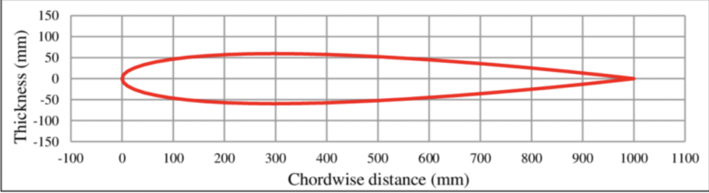
NACA 0012 Airfoil
2. NACA 2412: This refers to an airfoil with a camber of 2% of the chord length, which occurs at a distance of 40% of the chord length from the leading edge and whose maximum thickness occurs at a distance of 12% of the chord length from the leading edge.
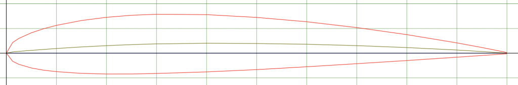
NACA 2412 Airfoil
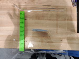
To introduce the airfoils to the flow and observe results, they have been screwed onto a sheet of acrylic. This attaching plane has been has been waterproof taped to the dividing plane. A protractor has also been etched into the attaching plane so as to help us change the angle of attack of the airfoil by a known value. For the sake of this experiment, the least count of the protractor used is 10 degrees. The plane also has flow converging geometries glued on so as to ensure that most of the water being pumped into the system flows over the airfoil and thus reduces mass flow rate error due to approximation.
The bottom left image shows a front view of the plane. Water flows into over the plane and enters from this side. The bottom right image is a plan of the attaching plane and shows the airfoil and protractor more clearly. To pick the angle, we match the tip of the airfoil with the marking of our choice.
-
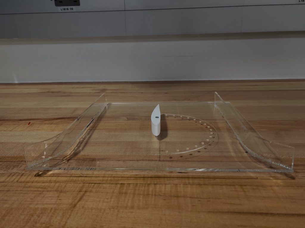
- Front View of Plane
-
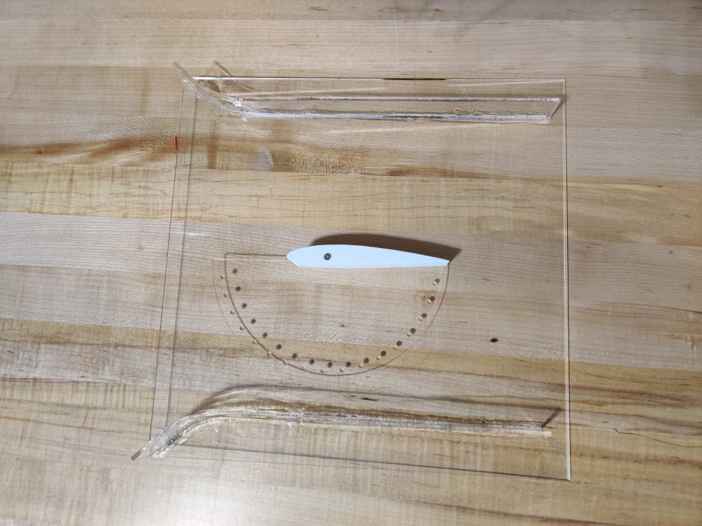
- Top View of Plane
One of the major challenges in this project was finding a mechanism to help vary the angle of the attaching plane in the direction perpendicular to the airfoil. Some ideas that were considered were:
- Tying fishing reel to the two ends of the plane and taping it to the edges of the fish tank. Aesthetic presentation was the main issue with this method.
- 3-D printing slots for the plate to rest on and gluing them to the inner walls of the tank. The main issue with this solution is that we only a few preselected angles could be obtained since the slot spacing changed the angle of the plane.
The best solution that was thought of was to 3-D print a scissor lift, glueing it to the base of the tank and rest the edge of the plane on it.
-
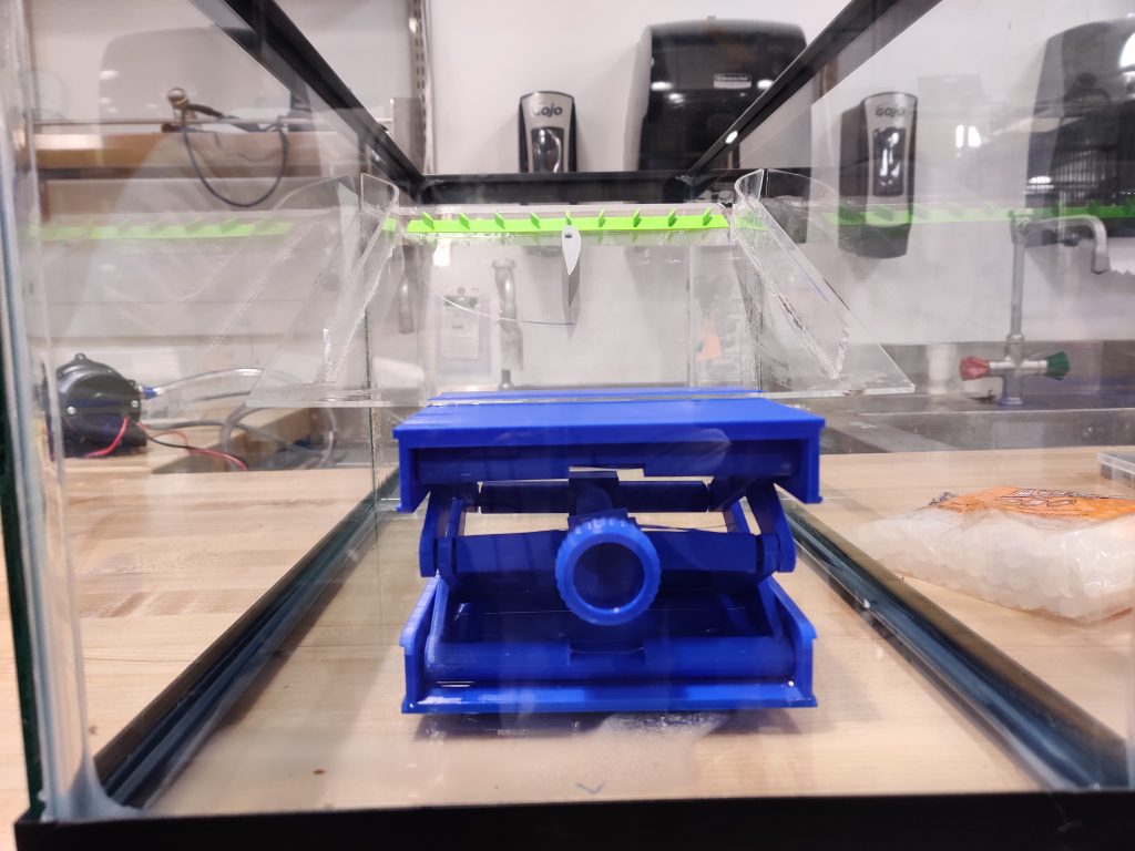
- Close-up of the Scissor Jack
To pump water over the airfoil, the EverFlo 5500 has been used as the pump of choice. This pump is a self priming 5.5 GPM pump. The process of pump selection was highly influenced by both the aforementioned Citadel paper as well as Dr. Cassandra Telenko, Georgia Tech. This pump however, requires a 120V power supply and a wire that can handle a 17A current.
-
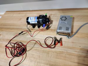
- An Image Showing the Wiring Setup for the Pump
Once wired, the pump requires fittings at the inlet and outlet. These fittings have been 3-D printed to fit the threads at the end of the pump. Teflon tape has been wrapped around the thread of the screws in order to ensure that they are water tight. The fittings are screwed on and then 1/2 in ID pipes are attached.
-
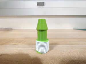
- 3-D Printed Fitting
The pump is designed to help circulate water in the system so that the reservoir overflows and water flows around the wing. However, this method does not allow for fully developed flow to form before it hits the wing. To aid the process of formation of fully developed flow, straighteners were designed and glued onto the attaching plane. It was 3-D printed ensuring that the thickness of the bottom layer was small enough to minimize interference with the flow. In this case, the base is 1mm thick. The straightener helps focus all he flow momentum towards the center of the plane, which is where the wing is screwed on.
-

- A CAD Render of the Flow Straightener
This section includes a comprehensive explanation of the system in action. From the empty tank, to the self circulating for visualization, a step-by-step procedure has been listed below:
- First, the pump is used to transfer water from a sink to the smaller reservoir section of the tank until it is filled. Then, the water is allowed to flow over the attaching plane until the other side of the tank has a significant but not excessive amount of water.
- The inlet tube of the pump is now submerged in the water present on the larger side of the tank. This allows for water to be transferred to the reservoir so that it overflows and falls back into the larger section, this allowing for a ‘perpetual’ system.
- As the water overflows, it flows over the attaching plane which has a flow straightener at its Leading Edge. The water flows through this structure and its momentum is focused towards the center of the plane.
- This water now flows around the airfoil on the plane and allows for the observer to visualize how it changes the direction of the water at different points along the airfoil.
-

- Close-up of the Scissor Jack
-
- Top View of Attaching Plane and Flow Straightener
5. Once the water flows over the plane, it falls and accumulates at the other end of the tank shown by the scissor lift in the image above. The other end of the pump is attached via a tube to this end and this water is redirected back to the reservoir so that it consistently overflows at the same rate thus allowing for a near constant flow velocity.
This is how the water keeps recirculating in the tank and we are able to collect data so long as the pump is kept on. A video of the system operating has been attached below. Special focus has been applied throughout the project to ensure that the fluid deflection due to the airfoil and the chosen angle of attack.
-
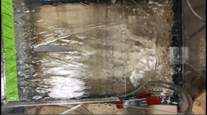
- Top View of Flow Over Airfoil
-
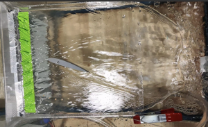
- Top View of Flow Over Airfoil with Angle of Attack