The framework of the body determines to a great extent the stability of the robot. The act of balancing can be achieved strictly if there exists a point of equilibrium for the robot. This means that there should be a positional state such that, at that point, the net force acting on the robot is zero. Ideally speaking, we expect the robot to be well-balanced when it is aligned vertically to the ground.
The factors that we should take into consideration while designing the robot are:
Light-weighted, so that the motors do not have to exert too much to restore balance.
Symmetrical design to keep the center of mass as close to the robot’s geometric center.
Sufficiently spaced to place all the electronic components and also ensure that the wirings can be adjusted.
We shall first discuss how the body needs to be designed and decide where the individual components get seated. Post that, we look into the circuital arrangement with the help of a schematic diagram, which explains the way in which connection is established between the electrical parts.
Chassis Design:
The CAD design of the chassis is designed using Solidworks and then manufactured with the help of 3D-printing. It is important to remember that chassis designs can vary depending on the sizes of the parts used.
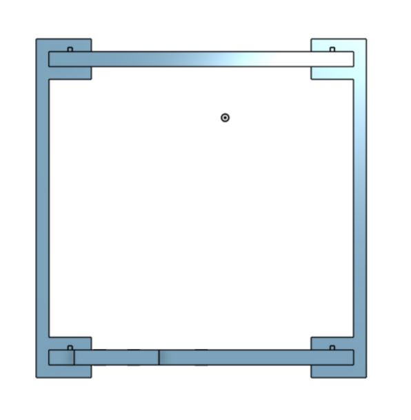
The model design here (Fig 1) is based on the dimensions of the specific components used in this project.
Fig 1: Base of the robot.
The base of the robot is rectangular with two extensions with holes jutting out sideward to make place for the motors to attach. Notice a faint rectangular marking on its face. That is the space provided for the power supply and the motor driver. Two smaller protrusions can be seen adjacent to the longer edges of the base. These will fit into our connectors as we will see eventually.
Fig 2: Top of the robot.
Like the base, the top of the robot (Fig 2) is also rectangular with no material extending on its sides. The top shall be used to house the Arduino and the breadboard with the MPU6050 sensor mounted.
Fig 3: Isometric and side view of the Connector respectively.
In Figure 3, a close observation would reveal one slot at the top and another at the bottom of the connectors. These slots have the same size as that of the protrusions on the top and the base of the robot. The rectangular pieces will slide between the ‘C’ shaped sections of the connectors and get locked when the protrusions fit into their respective slots.
The final assembly is demonstrated in Figure 4:
Fig 4: Isometric (left) and side view (right) of the complete assembly
Once you have the design complete with all possible revisions done, we now move on to 3D printing of the parts.
3D printing is a common and convenient method of manufacturing smaller parts. Its basic principle is that it uses heated plastic to mold into the required shape. The parts are built in layers, starting from the bottom and then moving upwards, after completing each layer. Several parameters can be adjusted while 3D printing, for instance:
Temperature of plastic
Desired thickness of the part
Rate of deposition of plastic
In order to print, we first need the G-code of our CAD design. Like every software-run machine, G-code is the language which the 3D printer understands. Many open-source software are available to generate the G-code of the CAD file (which must be exported with. stl extension). The Ultimaker Cura is one such software. In this project, I have used the printerCreality Ender 3.
More information on 3D printing can be found here.
Circuit Diagram:
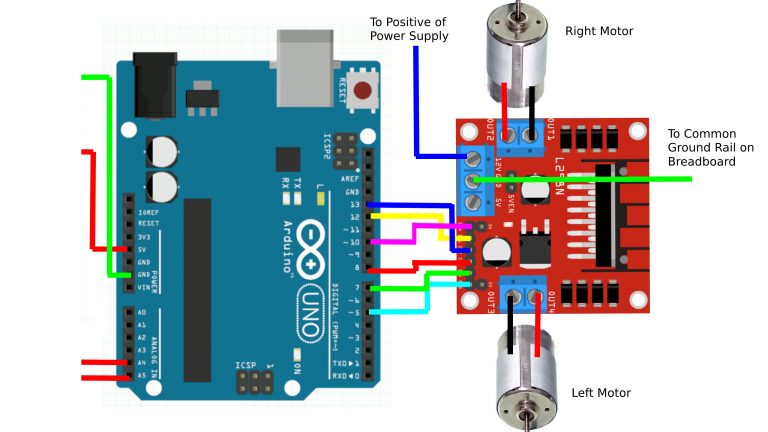
Figure 5 illustrate how the various components of the robots are connected to each other. The connection between the Arduino and the MPU6050 is a standard and can not be altered. However, the connections between the Arduino and the L298N motor driver can be manipulated by the user. Note that the speed of the motors should be controlled by analog outputs of the Arduino to enable variable speeds.
Fig 5: Connections between the electrical components
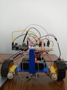
With this, we come to the end of the discussion on the overall design of the robot (Figure 6). The chassis’ structure was elaborated with the necessary conditions of symmetry and spaciousness being satisfied. A brief explanation was given on 3D printing, which covered its basic principles and provided a link to explore the topic further. We also understand the connections that are established between the electrical parts through the illustrations provided in the previous section.