
-
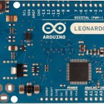
- Arduino Leonardo
-
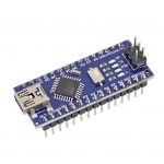
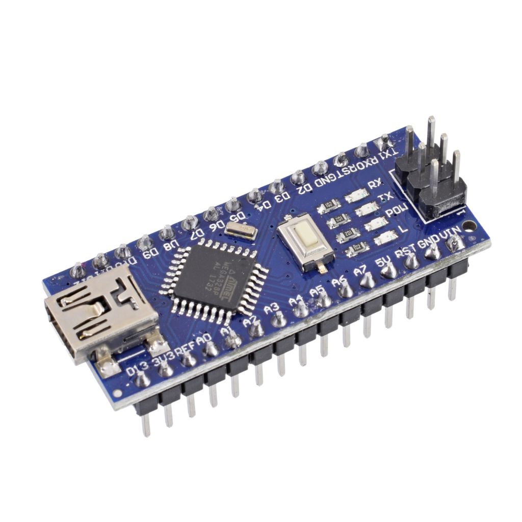
- Arduino Nano


© 2026 Duke MEMS: Experiment Design and Research Methods
Theme by Anders Noren — Up ↑