
Abstract
The breakout of COVID-19 is causing an extreme shortage of ventilators around the world, and with the pandemic still spreading it is difficult for factories to operate and full capacity and fulfill ventilator demands. As part of the community, the Graduate Capstone Laboratory is directing 2 teams of resources to explore different designs of ventilators that will be affordable, can be manufactured without advanced equipment, and mass-producible in a timely manner. The designs will be open-source and we welcome anyone to cooperate with us to solve the ventilator crisis.
Ventilator/Modular Vibrations & Dynamics Experiment
Introduction
Background/Motivation:
Before the COVID-19 pandemic, our goal was to create a modular experiment that reinforces the abstract dynamics concepts learned at every level. The experiment itself would have an easy way for students to customize the system to study each variable’s effects on the system, and for the students to be able to revisit the experiment later to study it at a higher level. The model for the experiment to best does this is a frictionless mass-spring-damper system as shown below.

The classic two-mass system with springs and dampers
This simple dynamics model is constantly used in lectures to demonstrate many phenomena and fundamental physics concepts. This experimental model gives hands-on learning to many difficult vibrations/dynamics concepts like Lagrange equations, resonance, modal shapes, structures, numerical analysis, frequency analysis, and MDOF systems. All of these topics are covered throughout the engineering curriculum as you can see from Duke’s curriculum map below.


Duke mechanical engineering curriculum map
These concepts are not only prevalent in the curriculum, but they are also very prevalent in the industry. Vibrations occur everywhere and many companies need engineers to minimize vibrations and to prevent resonance in dynamical systems like buildings especially during earthquakes, bridges, airplanes, rockets, and even cars and trucks.
As for personal development, we want to get a better understanding of the whole process behind developing and creating a product by actually going through the process. We want to gain proficiency in the various technical skills needed in the engineering industry like making CAD drawings, prototyping, ordering material, sketching, modeling, and creating simulations.
Why is this project relevant?
Ventilators are essential for treating patients suffering from COVID-19, and due to the recent pandemic, many hospitals throughout the globe do not have enough of them. Ventilators are in high demand right now, but they usually cost around $25,000. So, many organizations and people are designing and creating cheap, simple-to-make ventilators for those patients in need.
This project’s goal is to provide a cheap, simple alternative to the expensive ventilators needed for treating patients while creating a base that allows the ventilator to be easily converted into a modular dynamics experiment for undergraduate/graduate students.
Theory:

The equations of motion and schematic for a two-mass frictionless system commonly seen in many dynamics courses and the fundamental model in our ventilator
For the ventilator, we will only be using one mass and not incorporating any springs or dampers; however, the AmbuBag’s resistance to compress with act as a damper. The slider holding the puncher will be mass 1 in this model while the in-line slider-crank will provide the oscillating force.
Students could arrive at these equations using the Lagrangian method or Newton’s method and using numerical methods on the actual experimental system to find the solution to this EOM. By adjusting the damper, springs, and masses, they can see how each term affects the equations of motion as a whole. Furthermore, they could have an exercise where they need to find the right springs, dampers, and masses on mass 2 to zero out vibrations from mass 1.
Shown below is the equation of motion for an object connected to a crankshaft engine:
![]()
Where R is the radius of rotation, a is the angle of the crank measured from the top dead center, and L is the length of the shaft.
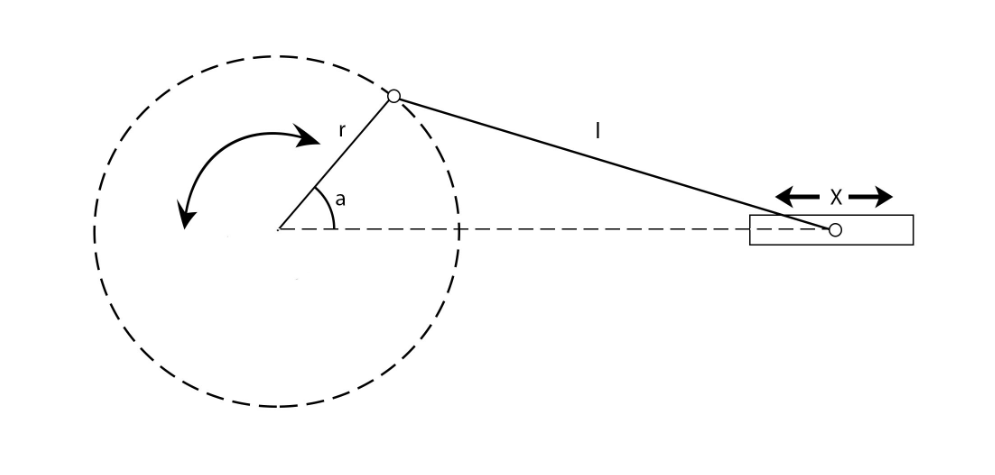
This will force the slider to oscillate sinusoidally on the rails. By adjusting r, we can get a different amplitude of oscillation and by adjusting the speed of a (by adjusting the rpm of the motor) we can set a frequency.
Functional Requirements for this ventilator:
- Simple and cheap: Hospitals around the world are in need of ventilators, and our goal is to fill this need in a cost-effective way. Keeping the design cheap will make it easier for the hospitals to get the ventilators, and making it simple will allow us to produce more.
- Safe for patients: While being simple and cheap is important, we cannot sacrifice the safety of the patients. Despite the desperate need for ventilators, we cannot jeopardize the people in need of them. There are many minimum set of requirements for a ventilator to be safe for patients:
- The respiratory rate must be between 8-40 breaths per minute
- The air volume pushed into the lungs must be between 200-800 mL
- The inspiratory/expiratory time ratio must start around 1:2
- Pressure detection or Trigger sensitivity in case their pressure gets dangerously low.
- Maximum pressure must not exceed 40 cm H2O
- PEEP of 5-15 cm H2O
- Manual control must be available if the patient needs attention
- Alarm in case the patient needs attention
- Long-lasting. The ventilator needs to function with these requirements for a long period of time.
- Must work with many AmbuBags: There are many versions of Ambubags with different diameters and lengths, and the ventilator must work well with most if not all types since we are not supplying the bags just the device that compresses them.
- Adjustable frequency and amplitude of oscillations: The flow of air and the amount of air per breath depends on the state of the patient which can vary moment to moment. The medical staff must be able to adjust the airflow into the patients to what is best for them.
- Lightweight (<15lbs): The ventilator must be lightweight for easier transport so it can get to hospitals easier, but more importantly it needs to be lightweight so it can be easily moved in the hospitals themselves. Hospitals are having to constantly rearrange rooms to fit more beds, and they would have to rearrange the ventilators as well.
- Easily modifiable to host dynamics experiments: The original goal of the project was to create a modular dynamics experiment as described earlier. Once the pandemic is past us, we want this design to be able to become the mass-spring system described before to help students learn about the dynamic systems and concepts they learn in lectures.
Design Process and Planning:
Initial ideas and quick thoughts on possible designs.

We decided to not do the “straps” design or “Rod on Hinge” design because they could not be easily modified to be mass-spring experiments. The puncher models allow us to use a slider platform that can be used as a mass for the mass-spring system. All we need to do is add an attachment to hold the spring and the damper.
Concave Compressor:
Our first thought for the puncher was a concave AmbuBag compressor. At first, we believed matching the curvature of the compressor to the curvature AmbuBag would have allowed for the best compression of the bag. However, after some testing with a concave compressor, we found that it requires much more force to compress than the other models.

AmbuBag in blue/ slider is red/ puncher is green
Convex compressor:
An immediate advantage we noticed from the convex model is that the force required to compress the AmbuBag was much less than when we used the concave model. The convex model has a smaller area first touching the AmbuBag which breaks the surface which then makes it easier to compress.
While the force needed to compress the bag isn’t something to worry about if you have a strong enough motor, many people may be using salvaged motors (e.g. from windshield wipers) that may not be strong enough.
For the convex model, we contemplated two possible designs.
Small puncher: Our first design for a convex puncher was a small puncher with a radius of curvature of R = 20 mm.

AmbuBag in blue/ slider is red/ puncher is green

While it prints very quickly due to its small size, this design does not compress the AmbuBag enough. There is not much air output from the AmbuBag.
Long puncher: Our second(and current) design for the convex puncher is shown on the right. The height being the most notable change which is what fixes our issue with the small puncher. The height allows for more complete compression of the AmbuBag.
In the end, we chose the long convex puncher. The convex curvature allows for an easier compression of the Ambu Bag, and the longer design compresses the bag more completely.
Should we have both sides with punchers or just one?
Many other institutions and companies have incorporated compression from both sides of the AmbuBag. While at first glance, it may seem that two punchers would be more effective to compress the bag, there is a trade-off for our case.

An example of concave compression from both sides on the left/ An example of concave compression from one side on the right.
Because we are tied to using the slider on rails to be able to use the base of the ventilator to host dynamic experiments, adding another pusher on the other side will significantly increase the size of the ventilator. Plus, it would require another motor which makes it much more difficult to assemble and more expensive to produce.
We have come up with a one-motor-two-pusher design, but they are in very early stages. We plan to design ventilators with these ideas and to build them to test the difference between using one puncher and two punchers.
One advantage of the two-pusher design is that it will require another slider on rails which will be needed for conducting two-mass system experiments once this project transitions.
As of now, we have chosen to keep the one-pusher/wall design. The effectiveness of the bag’s compression is not hurt by the simplicity of our current design. Nevertheless, we do plan to design both ventilator types to compare and contrast.
History and Progress:
Before we began to start designing the ventilator, we were designing a two-mass system that would have been used for undergraduate/graduate lab courses to supplement the material learned in many of their courses like resonance, vibrations, and many other dynamics topics.
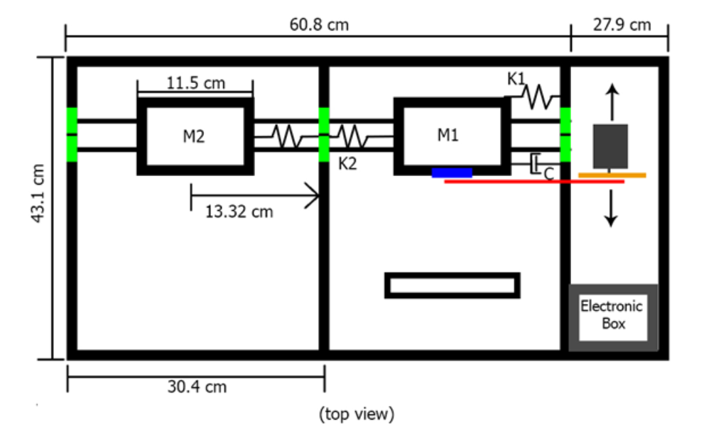
Schematic of the original experiment for the two-mass system with springs and dampers
The schematic is shown above. We were using sliders on rods as the masses. The slider bearings on the rods provided a good frictionless model. We planned to have these sliders connected to each other with a spring and one of the sliders connected to the wall with a slider and damper. All springs, dampers, and masses would be easily interchangeable with other parts that would have different spring constants, masses, etc.
The first mass would be forced by a DC motor which was connected to the first mass with a crankshaft and a motor arm in an in-line slider-crank configuration. The motor would be rotating in the vertical plane.
Once the COVID-19 pandemic began to affect the globe and the shutdown began, we changed our goal to be to design a cheap, simple ventilator. However, we did not want to abandon all of our previous work with the mass-spring system, so we decided to create a ventilator that could be easily modified to become the mass-spring system that can be used in undergraduate/graduate lab classes.
We based our design of the ventilator around a slider on rails oscillating sinusoidally due to a slider-crank setup which was the fundamentals of our original project. We began our first design with a simple slider on rods connected to a crankshaft which was connected to a motor arm.

Simple first design
We retain the slider on rails we used on the original project, but now we have the Slider-crank rotating on the horizontal plane rather than the vertical plane. This was done to reduce the possible interference the motor arm and crankshaft will have with the rod supports.
These parts are very simple and served as placeholders to allow us to design the rest of the ventilator without having to know every dimension of the original slider. As the project progressed, we replaced the place holders with the actual parts we printed and used.
Once we had this template for the ventilator, we designed an attachment to the slider that will hold the convex pusher and will be attached to the crankshaft. We called this attachment the “D-stand”; the reason being that it has a Duke D on its base.

D-Stand
The current design of the D-stand is shown above. It was designed to be easily attached to the slider with four M5 screws through the holes near the Duke D. These screw holes line up with the screw holes on the provided slider. The top of the D-stand allows for puncher attachments to be installed, so when we reach the testing phase, we could test all the different puncher models discussed before to determine the best puncher that optimizes air output and requires a minimal amount of force to compress the AmbuBag.
The D-stand is designed to have its curved back sticking out of the slider. This was done so that the crankshaft can be attached to the D-stand itself rather than the slider. This is shown in the pictures below.

In the future, once we plan to remodel the ventilator to serve the lab course, we will keep the concept of the D-Stand. Where it attaches to the slider but allows us to attach parts to it. We will incorporate attachments to insert springs, dampers, and masses.
Next, we focused on designing the crankshaft and motor arm to replace their placeholders in the design. At the moment, we had a “dog-bone” crankshaft where each end had a spherical bearing (inner radius = 4.9 mm / outer radius = 9 mm). We feared this design would cause instability while the slider oscillated, so we created a design alternative. A ‘dog-bone’ crankshaft, but with two heads on one side. The two designs for the crankshaft are shown below.

During the testing phase of our project, we will run experiments with both designs and compare the performance of the ventilator.
The motor arm for the ventilator was taken from the motor arm we designed for the original project. Below shows the original design (on the left) and the current design (on the right). We elongated the arm so that the amplitude of oscillations would be 4.5 inches (so the AmbuBag would be fully compressed then fully decompressed). The arm was also thickened so that it would be sturdier while it pushed the system back and forth.
The slider itself was the only part left that needed to be replaced for there to be no more placeholder parts in the design. We already had sliders with rod bearings available to us, but they posed an inconvenience. The screw holes used to install the D-Stand were overlapping with the screw holes that attached the rod bearings. So, we designed a new platform for the slider. This platform had to be wider so that the screw holes needed to install the D-stand are not the same as the screw holes needed to attach the rod bearings.

Above is the current design for the slider platform (left) and how the D-stand and provided rod bearings attach to this platform (right)
The first design for the actual part compressing the AmbuBag (the puncher), was small and convex that had an extension on the back so it could be installed on the D-stand. Its radius of curvature was 20 mm. The puncher alone and the puncher attached to the D-stand are shown below.
Quickly after designing this puncher, we anticipated two potential problems with implementing this puncher. the first being that it was very small and may not be able to compress the AmbuBag adequately. The second being that the puncher only extends 42 mm while the AmbuBag’s diameter is 125 mm, so when the puncher compresses the bag the completely, the bag will wrap around the D-stand as well as the puncher.
To solve the first problem, we designed a new puncher that was much taller. The height of the new puncher is 120 mm while the old one’s height was 40 mm. This new design is shown below. Tests must still be run in order to actually see the difference in the AmbuBag compression between the two designs.
To make it easier to break the surface of the bag into bending, we had the front of the pusher come to a sharp edge as seen in the right figure above.
To solve the second problem, we redesigned the puncher to extend about 100 mm away from the D-stand, so that when the Ambu Bag is compressed it will wrap around the arm rather than the stand. We modeled two possible designs that will solve this issue. The first, shown below, consists of two parts: a part that slides onto the stand with a dovetail, and the other part is the puncher described before with a long arm with a dovetail insert.

The second design consists of two parts like the last design, but the difference is that the part that slides into the D stand is the extending arm. The puncher then is attached to the arm with two M4 screws. This design is shown below.
We chose to use the second design because it makes it easier to install different punchers. When 3D printing new punchers to test out, we will not have to print out as much as we would for the dovetail design. This design will be more stable than a dovetail.
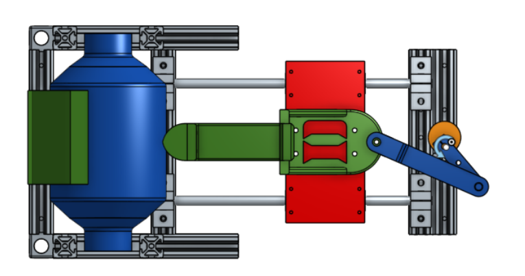
The Current Design:
Shown below is the current design of the entire ventilator. The design is bulkier than it could be due to the primary goal of this ventilator to be easily modifiable to become a mass-spring system for dynamics undergraduate/graduate labs.
The last thing to design for the ventilator is the AmbuBag holder and wall. These parts will hold the bag still as the puncher compresses it. It needs to hold it still and designed to easily remove the AmbuBag if needed. There are some preliminary designs on the model, but more work needs to be done for it before printing any parts. Regardless, the main mechanism, the compressor itself, has been designed and most parts have been 3D printed as of now.
The immediate next steps are to print the rest of the parts and assemble the compressor to be tested. While the compressor is being tested, we will design the AmbuBag holder and wall to then be printed and tested.
Project Management:
Alejandro: Ideation and designing of the original project, ventilator project decision making, designed CAD drawing of the ventilator, tested printed parts and redesigning, wrote webpage contents.
Cheng: Ideation and designing of the original project, ventilator project decision making
________________________________________________________________________________________________________________________________
Prototyping
- Parts, Bill of Materials
- Make sure you use a system schematic to label the parts you purchased/procured
- Why were these parts necessary? Could you have used different ones? Why or why not?
- Manufacturing processes used
- Also, discuss which processes you would recommend if you were building many more units
- Think about design for assembly, manufacture, maintenance/servicing
- How much have you considered the user experience?
Testing/Experimentation
- Preliminary results
- Debugging and shake-down of experiment
- Make sure all the systems communicate and work
- Analysis, Discussion
- Your results may not be what you expected
- Consider why this may be the case
- If you are able to get data that can be analyzed rigorously (not expected), what methods would you use to reduce the information into generalizable knowledge?
________________________________________________________________________________________________________________________________
Conclusion and Future Work:
Lessons Learned:
I have learned a lot from this course and working through this project. The hands-on and independent nature of the course was intimidating at first, but because of this, I have learned several important lessons that will help me once I begin my career in the industry. Not only has it prepared me for the future, but it has improved many general skills that will be helpful throughout my life and academic career.
- Setting strict deadlines for myself: In the future, I may have the liberty to work at my own pace, but it is important to set intermediate deadlines for yourself and your team to meet. Otherwise, without this structure, I run the risk of procrastination and an unorganized project. This was especially important once the lockdown began, and I was at home.
- Take notes often and of all your progress: This saved me a lot of time, but could have saved me a lot more if I implemented it better. It is best to write notes down of intentions/ changes made, or anything that would go into a final report as soon as you can because that is when your thoughts are clearest about the progress. Plus, having detailed and thorough notes can be very helpful when revisiting a project or passing it on to a new team.
- When you need help, ask for it: I would often shy away from asking for help fearing that it would make me seem incapable. This course has taught me that it is okay to not know everything even if it is something simple.
- Don’t shy away from new challenges: At first, this course intimidated me since I had no prior experience as an engineer. I never created a CAD drawing, assembled a prototype, or many other fundamental engineering tasks. Despite this, I not only learned how to do many of these tasks, but I also enjoyed doing it.
I plan to continue this project in the summer, where I plan to finish this project and hopefully transition into the modular experiment we originally planned to make. Moving forward, I will keep following the lessons I have learned.
Future Direction:
After rigorous testing and prototyping of the ventilator, we aim to add several key features to make it easier for user-use and to be safer for patients. For example, we hope to include emergency stops and alarms in case there comes a situation where a patient is in danger or needs a more sophisticated ventilator. We also plan to include a pressure sensor that can be installed into the AmbuBag to monitor airflow. With an Arduino kit, we can program the rpm of the motor (the frequency of the compression) to be dependent on the reading of the pressure sensor.
Most importantly, we will test the ventilator to fit the minimum requirements for ventilation detailed earlier on the page (under functional requirements). Adjustments will be made to the design to make sure these requirements are satisfied. More circuitry is required as well to implement sensors to monitor the patient’s respiratory rate, tidal volume, I/E ratio, and other important variables that must be monitored for the safety of the patient.
As said many times before, the ultimate goal for this ventilator design is to become the base for undergraduate/graduate lab experiments. The slider on rails provides a great model for the frictionless mass system seen in many dynamics courses. Plus, the oscillatory forcing from the in-line slider-crank allows us to set up experiments to study vibration concepts.
Some of the experiments available with this foundation include:
Resonance:
Resonance is a major concern for many engineers in many fields. It can occur on the bridges we drive on and the planes we fly on, so many engineers must take this phenomenon into account when designing. With our experimental setup, we can create resonance to demonstrate to the students its catastrophic effects and what they could do as engineers to prevent it.

Structure integrity studies:
Simply by securing a three-level structure held by flat beams (as shown in the right figure) on the slider and increasing the rpm of the motor, we can mimic a building suffering from vibrations. This is a common issue with buildings located in earthquake-prone areas or with skyscrapers. The experiment can challenge the students to develop methods to dampen the vibrations of the structure. Potential solutions could be a pendulum, water tank, and many others. This experiment will give them experience with designing their own method to solve an engineering problem.
Design changes needed:
While we can keep the slider, crankshaft, motor arm, and rod supports when we switch from the ventilator to the modular experiment, there are still many modifications to make. To make the classic two-mass system, as shown before and again below, we need two sliders, springs, and a damper, so we will have to create another slider on rails next to the original. Then we need to have the springs and dampers attach to the walls and sliders. This is where the D-stand will have to be modified.
The D-stand will have to be redesigned to have components where springs and dampers can easily be installed and removed, so students could change them out while doing the experiments. It will also have to be modified to hold masses. On the other hand, the puncher and arm attachments will no longer be needed.
Acknowledgments
First and foremost, we want to thank all of the essential workers and hospital staff that are working hard long hours to help us all get through this global crisis. Without their courage and selflessness, the situation would be substantially worse.
We want to thank Dr. George Delagrammatikas for his guidance and commitment to allow us to continue our course project despite the mandated shelter-in-place. We also want to thank Dr. Sophia Santillan and Dr. Nico Hotz for their help throughout the course.
References
MIT. (2020, May 1). MIT Emergency Ventilator (E-Vent) Project. Retrieved from https://e-vent.mit.edu/
Domus. (2020, March 23). A 3D-printed ventilator prototype from an open-source project. Retrieved from https://www.domusweb.it/en/news/2020/03/20/open-source-project-to-build-a-medical-ventilator-autonomously.html
Rice University Oshman Engineering Design Kitchen. (2020). ApolloBVM- Emergency Use Ventilator. Retrieved from http://oedk.rice.edu/apollobvm/
Teknic Inc. (2020 March 20). 1st prototype running! Easily manufactured, low-cost ventilator prototype for COVID-19 patients [Video file]. Retrieved from https://www.youtube.com/watch?v=3ssVoWEVxw4
The Times of India. (2020, March 26). Mahindra’s ventilator will cost Rs 7,500 [Video File]. Retrieved from https://www.youtube.com/watch?v=apocxLHlXPs
Vanderbilt University. (2020, March 27). Open-source ventilator design [Video File]. Retrieved from https://www.youtube.com/watch?v=vdLXp7uGFX4
Rice University. (2019, May 6). Rice engineering breathe new life into ventilators in low-resource settings [Video File]. Retrieved from https://www.youtube.com/watch?v=1t2t8d8xtD0
MIT. (2020, April 9). Key Ventilation Specifications. Retrieved from https://e-vent.mit.edu/clinical/key-ventilation-specifications/
Alexander, A., & Belanus, K. (2014, June), Construction of a Vibrating Structure for Demonstration of Vibration Measurement and FFT Analysis Paper presented at 2014 ASEE Annual Conference & Exposition, Indianapolis, Indiana. https://peer.asee.org/20208
Sudhakar, K. V., & Majewski, T., & Maus, L. (2006, June), Innovative Experimental Practices In Vibration Mechanics Paper presented at 2006 Annual Conference & Exposition, Chicago, Illinois. https://peer.asee.org/428
Sala, A. L., & Echempati, R. (2011, June), Performance Assessment of Undergraduate Vibrations Course Paper presented at 2011 ASEE Annual Conference & Exposition, Vancouver, BC. https://peer.asee.org/18866
Darvennes, C., & Pardue, S. (2001, June), A Modular Approach To Vibrations Paper presented at 2001 Annual Conference, Albuquerque, New Mexico. https://peer.asee.org/9569
Appendices
- Calibration procedures for all sensors
- Include data sheets
- Experimental procedure
- Preliminary results (tables of raw data)
- Statistical analysis; sample calculations