
Like most CAD applications, SolidWorks has three types of documents, a Part, an Assembly, and a Drawing.
- Part:
- A part is an atomic component combining one or more solid bodies.
- A part cannot be separated internally, and all its internal geometries are fixed by user set dimensions. No internal movements are supposed to occur within this type of document.
- Assembly
- An assembly is a group of parts that are attached to each other through user defined dimensions and constraints within the assembly.
- Internal movements within the assembly could occur if needed. For example, an assembly resembling a vehicle could have its wheels rotating with respect to the stationary chassis.
- Drawing
- A drawing is essentially the same as engineering sketches/mylars that existed before the time of CAD to serve as references for manufacturers. Some CAD software (such as SolidWorks) allow direct conversion from 3D documents to 2D sketches, preserving geometrical properties.
See below for the SolidWorks popup window for file creation.

Pop-up window when creating a new file in SOLIDWORKS
With knowledge from previous sections, we can now look at the main working environment for SolidWorks
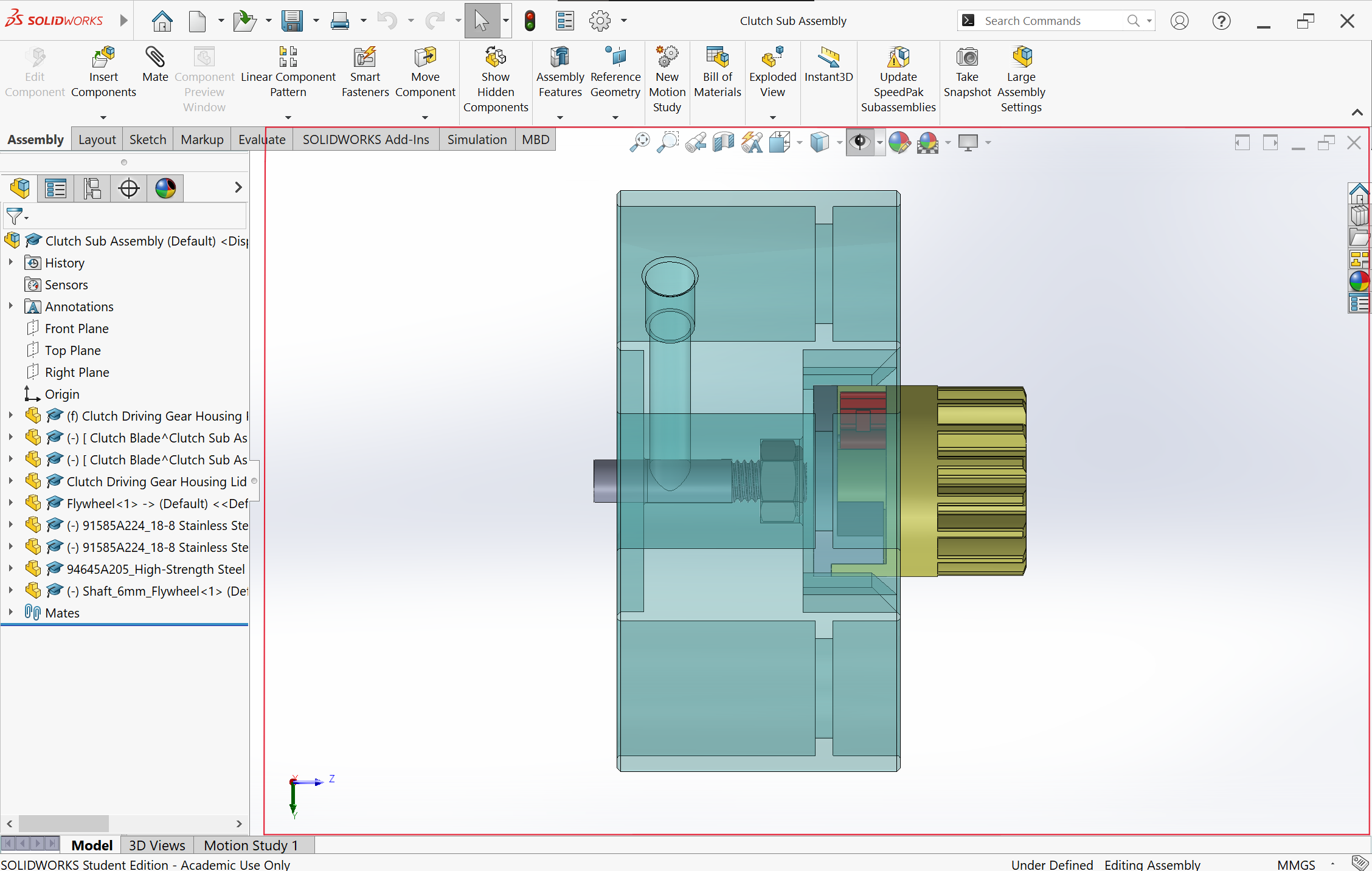
SolidWorks Main User Interface Window (Assembly) with Highlighted Scene
As the image shows, the scene, which where all the geometries are shown, is highlighted in the red box. In default for SolidWorks, the tool bar resides on top of the scene, while the feature tree is on the left side.
As a user becomes more familiar with SolidWorks, many other helpful features come into play. In this demonstration however, only the toolbar and the feature tree will be focused on as they are the most crucial in applying the SolidWorks platform for CAD.
Create a volume from a sketch based on a plane. The sketched 2D geometry serves as the shape of the volume’s cross area parallel to the starting plane. For an extrude, the volume will serve as a body of material added to already existing features. For an extrude cut, the volume will serve as a body of void subtracted from the existing body.
See below for a basic example of an Extrude and an Extrude Cut.

An extrusion is useful when creating a 3D body that resembles the projection of a 2D geometry. For example, to make a pillar, you can extrude a circle for a certain length.
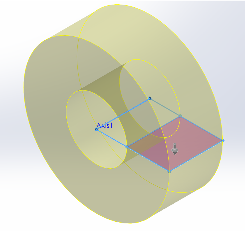
Create a volume by rotating a sketched, enclosed geometry around an axis. For a revolve, the created volume is a body a material added to existing features. For a revolve cut, the created volume is a void that subtracts from the existing body.
See below for a basic example of a Revolve and a Revolve Cut.
Revolve
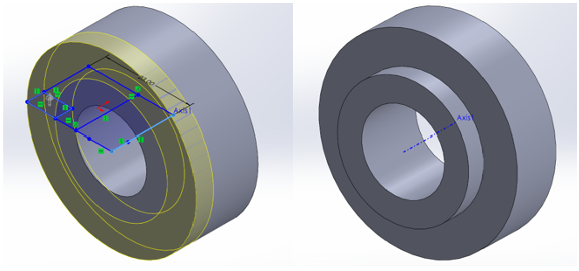
Revolve Cut
A revolve is useful when creating a 3D body that is circular in some way. For example, you can use revolve to make the base body for a nut, before refining the details using other features.
A Chamfer/Fillet can be applied to a sharp edge of a solid body to “grind” the edge down. Using a chamfer result in a small flat surface that replaces the original edge, while using a fillet result in a rounded surface.
Chamfer
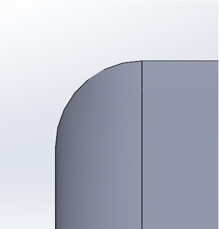
Fillet
The hole wizard is a powerful tool that makes creating mounting spot for fasteners in SolidWorks much easier.
While sketching a circle and then extruding it to cut through a set volume in order to create a simple hole may seem easy, in real-world applications, this method often falls short when dealing with various fastener types, given their frequent variations in size and shape.
The hole wizard automatically combines two sketches (one for the location of the hole and the other for its full geometry) to generate a much more complicated revolve-cut-volume, without requiring the user to manually define all dimensions driving the two sketches and the feature. Instead, the SolidWorks library contains dimensions of holes that are compatible with international standard fasteners, and all the user is required to do is to select the parameters based on the fasteners they are trying to match.
See below for an image showing the interface of the Hole Wizard feature and examples of parameters a user can modify.

When designing your system, it is likely that you would have to implement some non-custom standard parts due to various reasons. To check that they are compatible with your system, you want to make sure your customized parts have the correct dimension.
McMaster-Carr is a large distributor for hardware and their website offers CAD files for their products. To get access, simply go to https://www.mcmaster.com/, and search the component you want to look up. Clicking on the part number of the components will trigger the following popup window, and it provides the option to download 3-D SolidWorks model.

Import the downloaded model to your assembly and check the fitting to make sure components are compatible with each other.