Shear Center Experiment

Static Test Rig

In the previous module we tactilely deformed the 3D printed beams in order to qualitatively demonstrate the concept of shear center and its effects on the bending and torsion of doubly and singly symmetric concepts. The natural continuation of these qualitative experiments is to build a test rig that can perform repeatable experiments from which data can be collected and important quantities such as the elastic and shear moduli of the material can be experimentally determined using the theoretical concepts introduced.

The test rig is built using 80/20 Aluminum rails and 3D printed (PLA) reinforcements:

Static test rig where a servomotor progressively loads the beam and a Time of Flight sensor yields deformation data while load cells measure force from both bending and twisting. The adapter plate allows loading at various points along the radial axis of the beam

Control and Data Collection

As labeled above, the test rig employs a Teensy 4.0 microcontroller, a VL53L5CX time-of-flight imager (ToF), and 500 gram load cells all wired together with a breadboard. Please follow the above hyperlinks to purchase these components and view their schematics and documentation.

Arrangement of Teensy, Time of Flight Sensor, and load cell amplifiers

In the future, the breadboard could be converted to a PCB to make the test rig less cluttered and promote recyclability. 

Teensy

We chose to use a Teensy 4.0 over an Arduino as our controller because of our circuits memory requirements. A minimum of 90K of memory was required for the ToF firmware which far exceeds the Arduino Uno’s available 2K. The Teensy provides an abundant 1984K of Flash memory at half the price of an Arduino Uno.

Time of Flight Sensor

We use  the VL53L5CX time of flight sensor from SparkFun that returns a 64 pixel image of distance values from a diagonal field of view of 63 degrees. 

Grid field of view of Time of Flight sensor projected onto beam

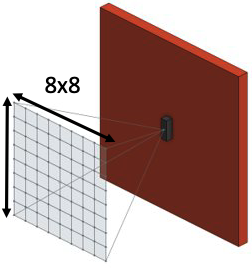
When plotting this 8×8 grid in 3D we can see clear trends from which we can determine  bending and twisting data for our beam using a planar least squares regression. By fitting a plane to the data we obtain rotation (deflection of the beam) as well as distance to the center axis.
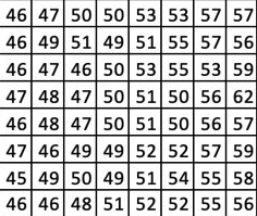
ToF Distance Output

The example raw distance output from the sensor doesn’t provide an easily identifiable trend with regards to the angle of our measured surface. When we plot the values in 3D, we can see a clear trend of the data, there is a  slope to the data. 

Initial 3D Plot of Distance

Initial 3D Plot of Distance

How do we obtain an angle from this data? We perform a Planar Least Squares Regression. With a plane fit to our data, we now can compare the orientation of that plane with respect to a base plane to establish an angle of rotation. By recording the distance to the center of the plane, we can also determine the amount the beam in our test rig has deformed as a result of pure bending.

Planar Least Squares

Planar Least Squares

Load Cell Calibration and Servomotor Programming

Using a known mass and a known geometry we can determine the output force with which to calibrate the load cell. Since we are using a microcontroller, we can automate the calibration routine by looping through our routine and adding the necessary calibration factor in small increments until our measure force matches our known force from our calibration mass.

With our load cells calibrated, our servomotor is then programmed to spin a drum to tension a cable until a predetermined load is reached to prevent damage to the load cells. At this point, angle and distance measurements can be recorded from the ToF imager for use in analytical calculations previously described.

Relevant Code

The code used to calibrate the load cells and Time of Flight sensor as well as run the motor can be found here: Code 

In order to run the code first download the Arduino IDE and paste the code into it. Once you have wired your Teensy to the specific pins, shown here, as well as the load cell and sensor, you can upload the code to the board and run it. 

For the motor, the R key runs until a specific load is reached, and O stops the operation.