As demonstrated by Professor Dowell in his book “A Modern Course in Aeroelasticity” the concept of shear center can be examined from an Aeroelastic (interaction between the elastic properties of the structure and the aerodynamic properties of the fluid) perspective with the following thought experiment:
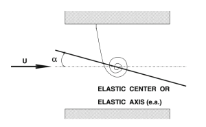
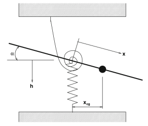
Thin plate attached to a spring at its elastic axis acted upon by an airflow of velocity U has an angle of attack alpha. Source: Dowell, E. H., Scanlan, R. H., Sisto, F., Curtiss, H. C., Jr., and Saunders, H. (April 1, 1981). “A Modern Course in Aeroelasticity.” ASME. J. Mech. Des. April 1981; 103(2): 261–262. https://doi.org/10.1115/1.3254897
If we attach a torsional spring to a plate at its elastic axis, which is the axis through the shear centers, and subject it to an airflow of velocity U. As the flow velocity increases, the angle of attack will increase thereby twisting the plate and compressing the spring until a failure speed is reached where the plate snaps. This is known as divergence and is exactly what happened over and over to the Fokker D8
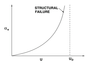
Relationship between flow velocity and angle of attack of the thin plate. The divergence speed is denoted Ud. Source: Dowell, E. H., Scanlan, R. H., Sisto, F., Curtiss, H. C., Jr., and Saunders, H. (April 1, 1981). “A Modern Course in Aeroelasticity.” ASME. J. Mech. Des. April 1981; 103(2): 261–262. https://doi.org/10.1115/1.3254897
Wind Tunnel
Updates
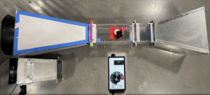
We were able to adopt the wind tunnel from a previous capstone project but needed to make some changes. Specifically, we added a new fan that increased our maximum flow rate from 10 m/s to 17.8 m/s. To accomodate we had to laser cut 1/4 inch acrylic and tape was added for an airtight seal. We also added a variable feed dial to control the flow rate.
New wind tunnel (above) compared to old fan section (below) and variable feed dial
Spring Dimensioning
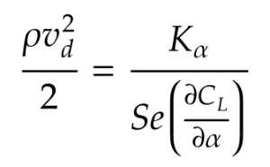
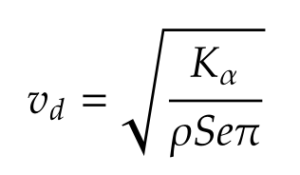
We need to determine the stiffness required for our spring and convert that from a torsional quantity to a normal quantity because our experiment was conducted with a compression spring. From Dowell,
Source: Dowell, E. H., Scanlan, R. H., Sisto, F., Curtiss, H. C., Jr., and Saunders, H. (April 1, 1981). “A Modern Course in Aeroelasticity.” ASME. J. Mech. Des. April 1981; 103(2): 261–262. https://doi.org/10.1115/1.3254897
where 𝜌 is the density of the fluid, vd is the divergence airspeed, K𝛼 is the spring rate of the torsion spring, S is the area of the flat plate, e is the distance from aerodynamic center to the spring connection point, and ∂CL/∂𝛼 is the rate of change of the coefficient of lift with respect to the angle of attack (2𝜋 for our purposes). Algebra yields,
There is one issue to note; K𝛼 is the spring rate of a torsion spring in units of Nm/ rad. We are using a compression spring in our experiment. Considering the equation of a force of a spring:
The dimensioned spring can now be placed in our rotary mechanism that connects the twist of the airfoil to the compression of a spring via gears. The loading on the spring is read by a load cell.
Spring mechanism which uses gears to transmit the increased angle of attack as rotary motion which in turn compresses the spring
3D Printing
For this aeroelastic experiment we want a stiff plate therefore we use PLA instead of TPU. The print speed should be set back to 60 mm/s when slicing.
Divergence
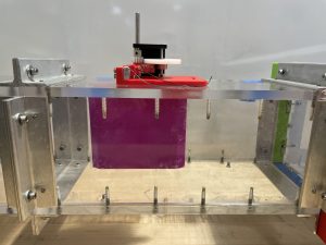
We place our plate-spring system into the wind tunnel
Thin plate in wind tunnel. Air flows to the right
using our variable speed dial we increase the flow rate U and see that the angle of attack begins to increase and the spring compresses (video below). Eventually, around our max speed of 17.8 m/s we observe what seems to be divergence as the plate snaps to the edge of the wind tunnel. This was actually caused by the slipping and structural failure of one the collets on the spring rod. The immediate next step in this experiment would be to make the mechanism significantly more robust to obtain accurate spring load readings and ensure repeatability.
Future Work
The experiment designed to demonstrate the concept of divergence for a thin plate using a spring can be extended to plates with control surfaces and asymmetric airfoils whereby a feedback loop to create an active flutter suppression mechanism.
Thin plate with control surface. Source: Dowell, E. H., Scanlan, R. H., Sisto, F., Curtiss, H. C., Jr., and Saunders, H. (April 1, 1981). “A Modern Course in Aeroelasticity.” ASME. J. Mech. Des. April 1981; 103(2): 261–262. https://doi.org/10.1115/1.3254897
These extensions add significant complexities to the aerodynamic behavior and calculations. As such, the theoretical and computational framework introduced below can be employed to predict the airfoils behavior.
Theory
Flutter
The study of aeroelasticity is concerned with the interaction of the elastic forces undergone by a solid mechanic, the inertial forces, and the aerodynamic forces acting on the mechanic. In our project, we are mainly concerned with a typically undesirable aeroelastic phenomena: aircraft wing flutter.
Consider aircraft wings as cantilevered slender plates, they typically undergo two types of motion
Bending relative to the cantilevered end (the wing flaps up and down) and
Twisting along the wing, the two motions causing the wing to vibrate.
When the wing is under an airflow, the aerodynamic forces from the flow acting on the wing further amplify the self-excited vibrations, increasing deflection along the wing. When the airflow reaches a critical velocity, the flutter speed, the wing breaks and can lead to catastrophic results on the aircraft. Thus, flutter suppression has been a vital element of aircraft wing design.
Aerodynamic Center
The aerodynamic center is the point on an airfoil where when aerodynamic forces are applied, the magnitude of moment remains constant at varying angle of attack.
The aerodynamic center is important as it eliminates the need to use the center of pressure to analyze forces on the wing, which can be a tedious process as the pressure distribution along a wing changes with varying angles of attack, and thus the center of pressure also moves.
Meanwhile, the aerodynamic center for a wing is generally fixed regardless of the angle of attack (in subsonic flows, it is located at a quarter of the chord from the leading edge: ac = c/4).
Aerodynamic Calculations
The Vortex Lattice Method (VLM) is used as a means to analytically determine the aerodynamic effects on an airfoil. Knowing the basic flight conditions (air density, flow speed, etc.), this method allows us to mesh the airfoil model and obtain the lift and pressure exerting on each mesh.
Mesh associated with Vortex Lattice Method. Source: Kenneth C. Hall. “Eigenanalysis of unsteady flows about airfoils, Cascades, and Wings”. AIAA Journal. Vol. 32, No.12, pp.2426-2432. Dec 1994
The code linked below computes the steady state lift and pressure distribution on an airfoil with given camber profile and at a predetermined angle of attack.
Formulas used for the VLM in the code are derived from references [8], [9], and [10].
Code
The code used determine the pressure distribution, resultant lift, and center of pressure for given flight conditions (such as flow velocity, air density) and wing shape (such as chor/span length, camber profile) can be found here: Code. To run it, first install MATLAB and ensure that your flight conditions are known and understood.