Unmanned Aerial Vehicles (UAV) such as drones are commonly used to receive real-time video feeds and images. However, when these drones are powered by artificial intelligence (AI), Machine Learning (ML) and computer vision, they can be made to do unimaginable tasks!
This project is a small step toward using swarm drones to successfully conduct 3D area mapping, object recognition in real-time, and finding optimal rescue routes before first responders arrive.
Working within the constraints of time (1/2 semester) and resources (limited drone swarm capabilities), our team recognized that we would not be able to accomplish this broad goal within the semester. However, we have worked on a smaller, feasible project where our main goal is to use images extracted from our drone camera to identify various shapes.
The Crazyflie swarm drones are be programmed to carry out various tasks (such as hovering, rotating, landing, etc…) based on the type of shape recognized. Once we have accomplished this, we can successfully say that we can pursue a higher-level of computation where the drones will be able to carry out the intended search and rescue operations mentioned.
Broader Goals
Some high-level tasks that future groups can aim to achieve are:
- Object Detection: Identifying civilians in need of help within the disaster site.
- Object Classification: Distinguishing firefighters, policemen, and first responders from civilians within a chaotic disaster zone.
- Categorization: Labelling objects in terms of criticality of rescue (deceased, pets, stuck individuals, unconscious individuals, etc.). Identifying these groups of people will help first responders decide quickly which areas/people to access first and map an optimal rescue plan.
- Tracking: Individual drones (from within the swarm) will be able to follow civilian movement and track them until they are rescued or guide them to safety.
If we accomplish these tasks using artificial intelligence in computer vision, we will be able to:
- Reduce the time taken by first responders to take action.
- Increase the number of lives saved at the time of disaster.
- Provide better assistance to first responders by being able to navigate through in-traversable spaces and calculate optimal paths to entry and exit.
Therefore, in the context of our Capstone project, have accomplished the initial “Shapes Recognition” and task completion objectives in order to demonstrate the potential broader impact of our future work.
LED Integration
Components
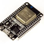
- ESP-32 WROOM Development Board (2.4 GHz Dual-Mode WiFi + Bluetooth Dual Core Microcontroller) – Buy it here
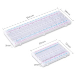
- Solderless Breadboard – Buy it here
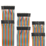
- Assorted Dupont Cables (Jumper Wires) – Buy it here
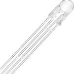
- RGB LED 4-Pin Diode Bulb – Buy it here
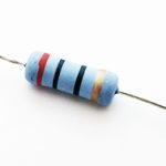
- Resistor Assortment Kit – Buy it here
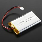
- Adafruit – Lithium-Ion Battery (3.7V 2000mAh) – Buy it here
- Programming Cable – MicroUSB (Type B)
[Note: For alternative ESP32 boards, check out the Hands-at-Home page]
Tools needed on hand:
- Soldering Iron Kit – Buy it here
Getting Started
In order to get started, it is important to know the basics of how the ESP32 microcontroller works. A complete guide on ESP32 and easy-to-follow tutorials can be found here.
For our project, we used an ESP32 DevKit v1 Board with an ESP-WROOM-32 Module.
RGB LED 4-Pin Diode:
The RGB LED consists of 4 pins (Red, Green, Blue, and Ground) and can emit any color on the spectrum by controlling the three primary color elements. These elements have a value ranging from 0 to 255.
You can explore the RGB values for some colors here.
Circuit Diagram
In the circuit below, we have used three 20Ω resistors for the Red, Green and Blue Pins. When replicating this, you can alter the resistance to adjust the maximum brightness you want to achieve.
The following wiring diagram was created using Fritzing.
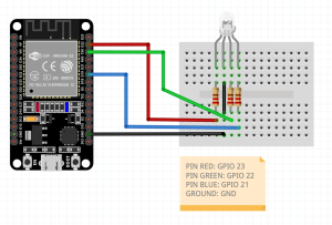
Circuit Diagram
Using Arduino IDE
To start programming the ESP32 Microcontroller, first make sure that the most recent version of Arduino IDE is downloaded and installed on your desktop. We have used Arduino IDE since it has the most community support and can be integrated across multiple platforms.
We followed this tutorial to use Arduino IDE to program ESP32 board.
Troubleshooting Advice:
- Make sure that you have selected the correct “Serial Port” within the Arduino IDE application. [Arduino IDE > Tools > Port]
- Make sure to install and select the appropriate Board you are using. [Arduino IDE > Tools > Boards > Boards Manager]
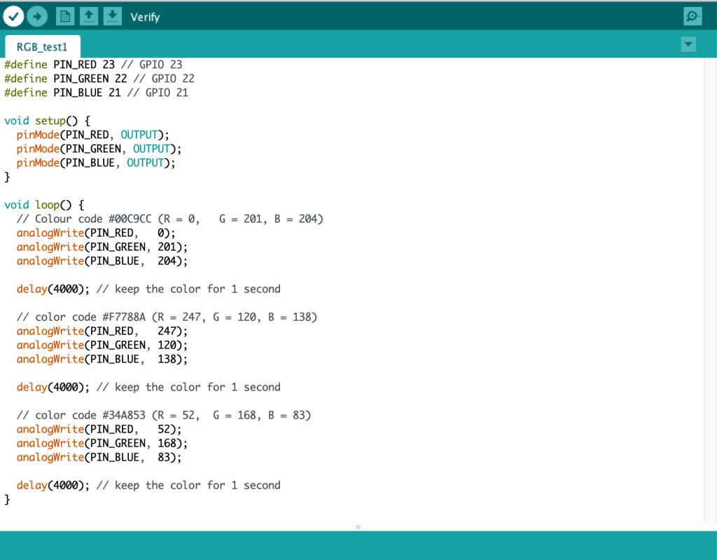
Run this basic code RGB_LED_Test to check if the circuit and LED are working correctly.
System Integration
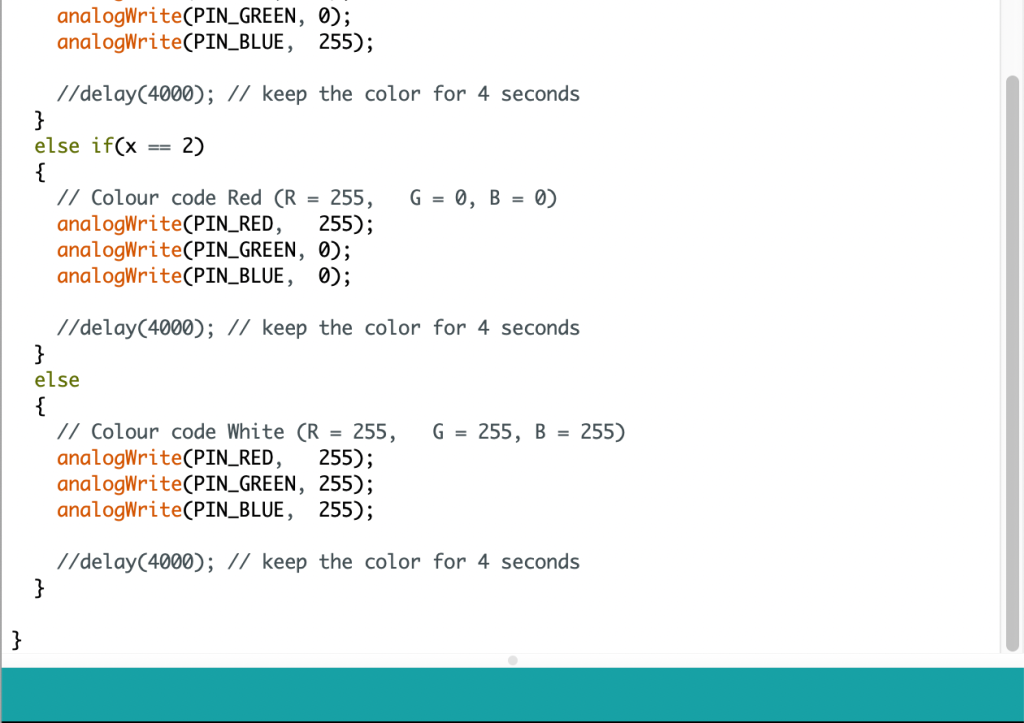
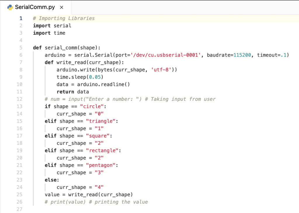
The next and final step in this project is to full integrate the LED with the ESP32 CAM (Camera Module) along with the Shape Detection program. Serial communication is a way to transfer and receive data one bit at a time from a computer through Arduino’s serial.
In order to accomplish this task, we decided to use a Python serial port extension called “PySerial”. An in-depth tutorial on how to install and use PySerial can be found here.
Check out the Arduino IDE code for Serial Communication here.

Check out the Python Code here.
Proof Of Concept
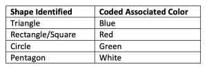
The video below shows an LED changing colors based on the shape detected by the ESP32 CAM (Camera not shown in the video).
In the computer screen you will be able to see a real-time video feed of the camera being pointed toward multiple shapes. The LED only changes colors when a shape has been identified correctly 10 times by the algorithm.
Drone Actions
Now that we have learned how to fly and control a swarm of drones and subsequently integrated the ML algorithm to the ESP32-CAM, we can explore the range of new capabilities that the drones have to offer!
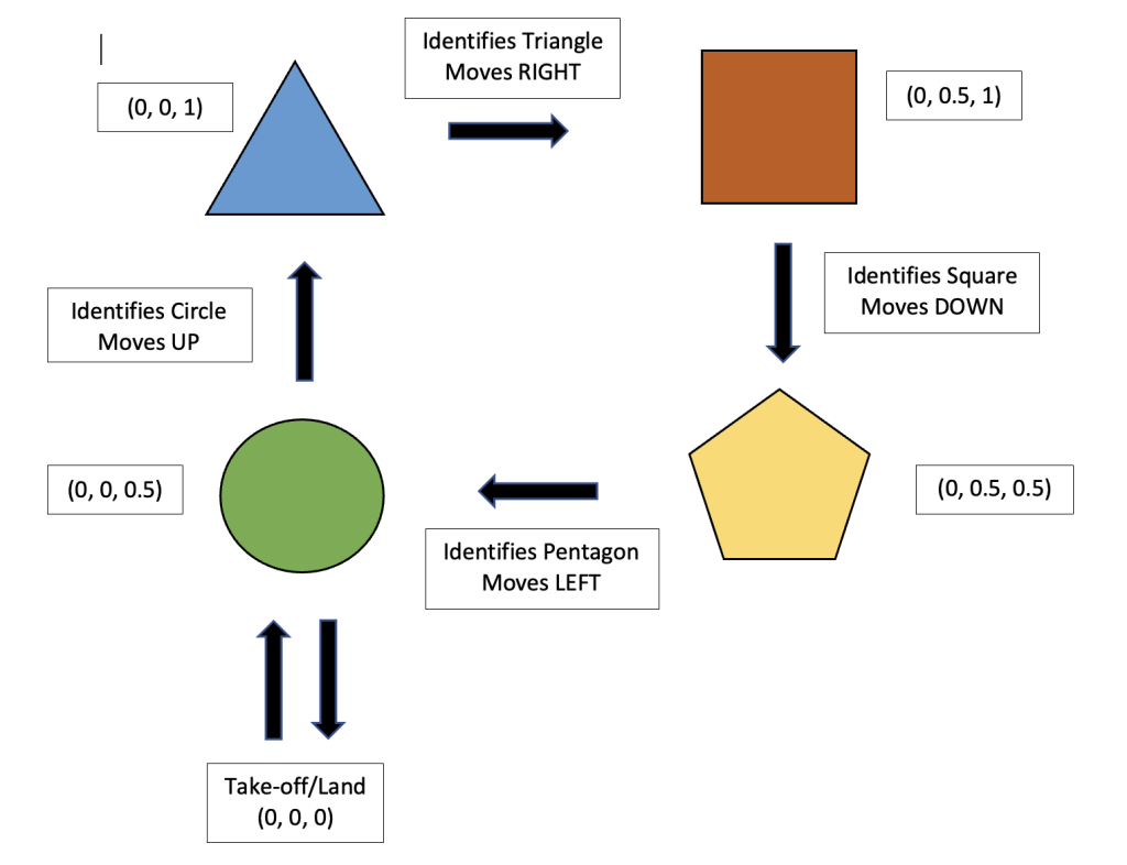
Our initial plan of action was to program the drones to fly in a rectangular loop as it detects various shapes as shown in the diagram below.
Code Structure
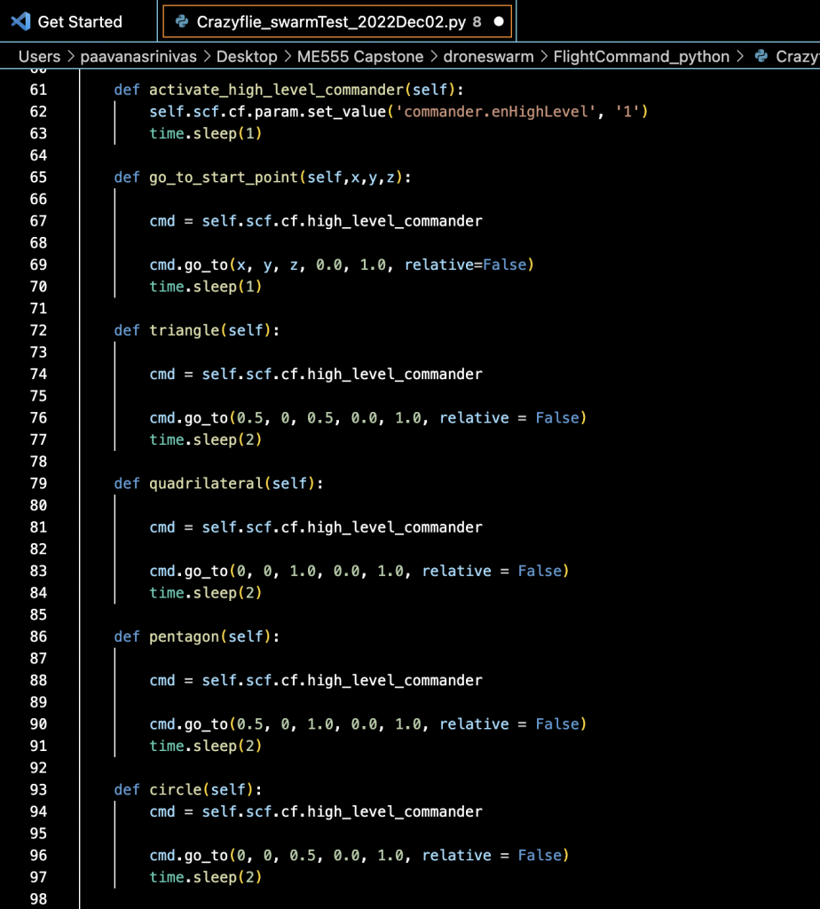
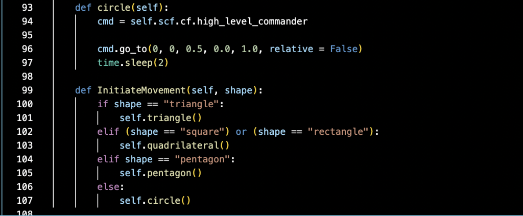
The following snippet of code was used to create hardcode the drones to fly to specific positions on a 3D coordinate system when a shape was recognized.
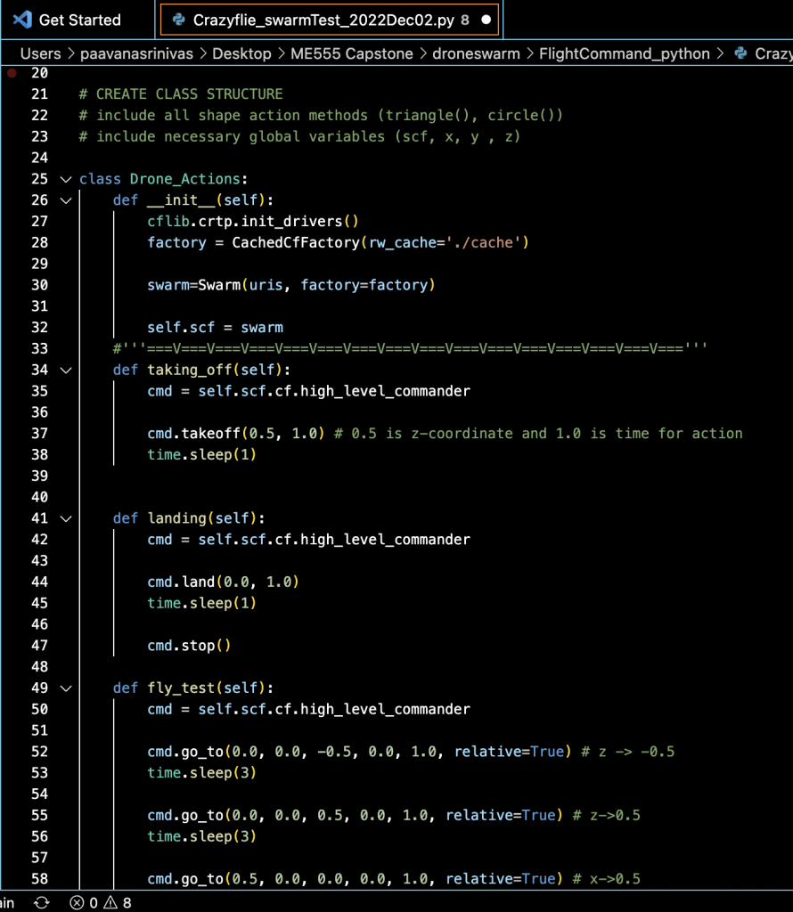
Proof of Concept
Let's take it one step further...
Once we successfully demonstrated the above actions, we decided to take it one step further by making a swarm of drones fly in the shape that it detects.
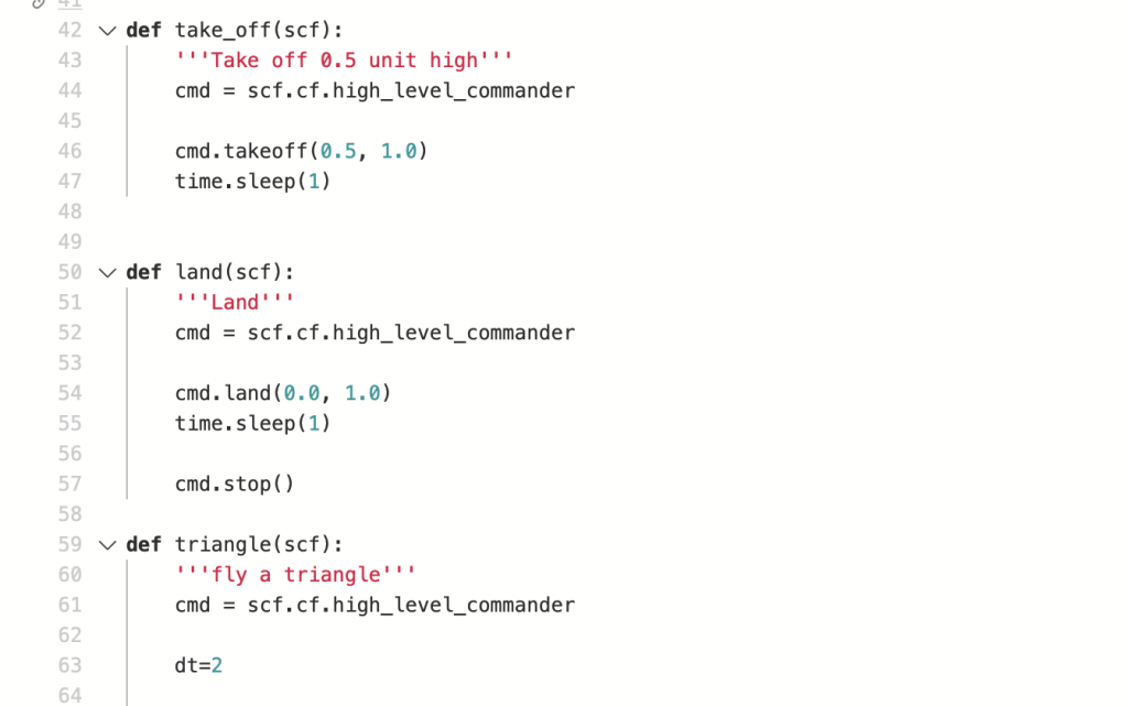
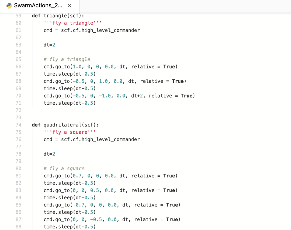
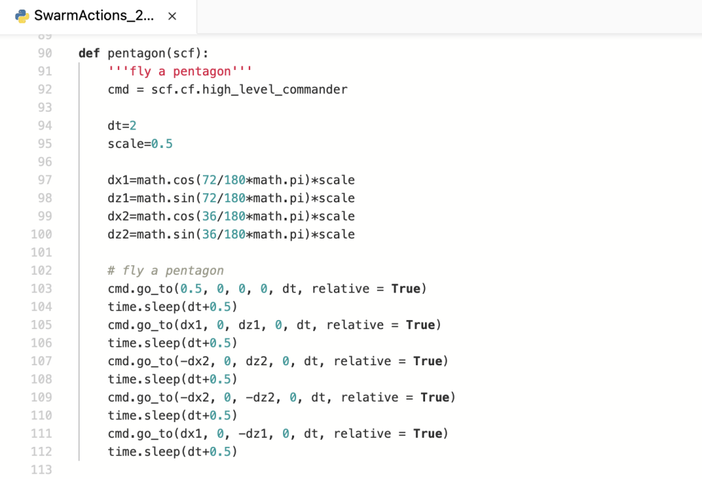
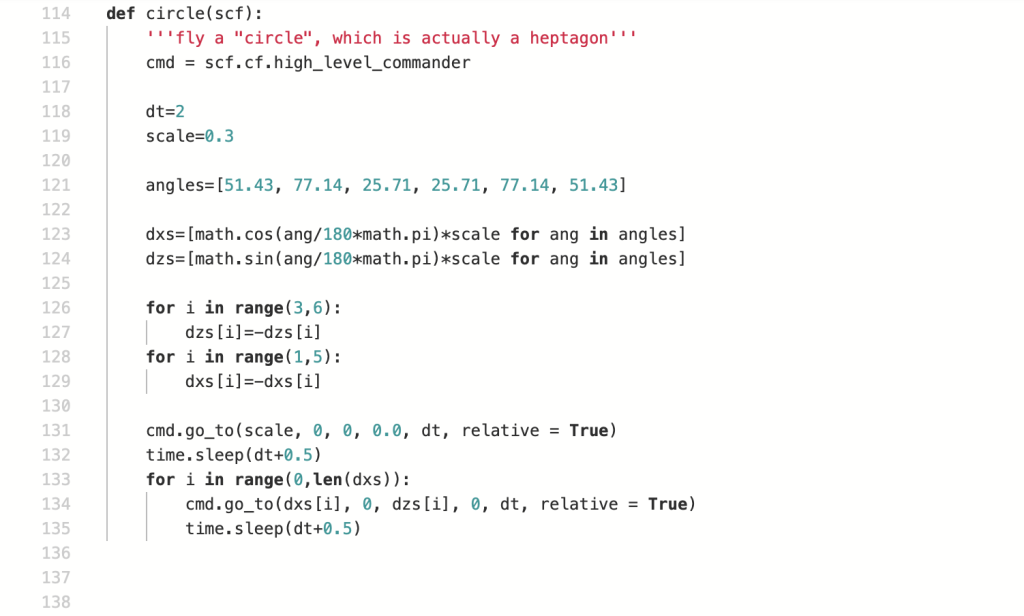
In the snippets of code below, you will see functions defined for each shape, and flight commands to replicate that shape.
