The Concept

armBOT
A custom-built, open-source six-axis robot arm is proposed in this work which is capable of recognizing and moving objects to a specific location while avoiding obstacles in its path. The robot is equipped with visual imaging that processes the location of a desired object and transfers it to a desired location. Object recognition is performed using a Convolutional Neuron Network (CNN) and object location, including depth information, is deduced via the camera. The robot arm avoids obstacles along the way by implementing the Rapid-exploring Random Tree (RRT) algorithm to reaches the goal point.
- Background/Motivation
- In the medical industry, a serious operation takes several hours. In this process, a doctor needs many assistants to provide delivery tools, which wastes a lot of manpower.
- We hope to design a robot that can replace the role of auxiliary personnel.
- Theory
- Using Rapidly-Exploring Random Tree (RRT) to do the motion planning
- Using Convolution Neural Network (CNN) to do the obstacle recognition
- Problem Formulation
- We need to complete a whole control system like the graph.
In eletronic part, we need use Arduino control one gripper and six joints.
 The gripper is controller by a DC motor when the joints is controller by a stepper motor.
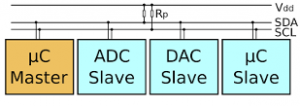
 To complete the control part, we apply I2C series in the electronic.
I2C (Inter-Integrated Circuit), pronounced I-squared-C, is a synchronous, multi-master, multi-slave, packet switched, single-ended, serial communication bus invented in 1982. It is widely used for attaching lower-speed peripheral ICs to processors and microcontrollers in short-distance, intra-board communication.(From Wiki).
From Figure blow, we could directly understand that I2C is using one master device to control several slave devices.
To complete the control part, we apply I2C series in the electronic.
I2C (Inter-Integrated Circuit), pronounced I-squared-C, is a synchronous, multi-master, multi-slave, packet switched, single-ended, serial communication bus invented in 1982. It is widely used for attaching lower-speed peripheral ICs to processors and microcontrollers in short-distance, intra-board communication.(From Wiki).
From Figure blow, we could directly understand that I2C is using one master device to control several slave devices.
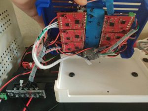
 To apply I2C and dirve our motor, we need a motor diver board. Here we use a designed board named TIC T500:
 We could see this board have both motor drive part and I2C part. And then we connect TIC board, motors and arduino with such a design below:
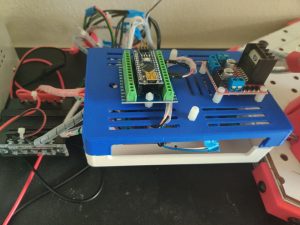
 The pratical vision:
The gripper is controller by a DC motor when the joints is controller by a stepper motor.
To complete the control part, we apply I2C series in the electronic.
I2C (Inter-Integrated Circuit), pronounced I-squared-C, is a synchronous, multi-master, multi-slave, packet switched, single-ended, serial communication bus invented in 1982. It is widely used for attaching lower-speed peripheral ICs to processors and microcontrollers in short-distance, intra-board communication.(From Wiki).
From Figure blow, we could directly understand that I2C is using one master device to control several slave devices.
To apply I2C and dirve our motor, we need a motor diver board. Here we use a designed board named TIC T500:
We could see this board have both motor drive part and I2C part. And then we connect TIC board, motors and arduino with such a design below:
The pratical vision:
About the specific Code, please see Motion-Planning in Github
To Solve the kinematic problem, we need introduce both forward and inverse kinematic problem. We Will start from forward part.
 We could see, based on the different angles of joints(assume the length of arms are fixed), we could get a relationship between the start point(base coordinate) and the terminated point(gripper coordinate).
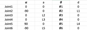 Now we could see a form of our DH table, which is the model of our robot arm.
This DH table includes 4 parameters: α, a, θ, d, each parameter have different functionality when we model the robot arm.
Now we could see a form of our DH table, which is the model of our robot arm.
This DH table includes 4 parameters: α, a, θ, d, each parameter have different functionality when we model the robot arm.  α:The angle that rotate Z axis by the original X axis.
a: The distance from original Z axis to rotated Z axis following original X axis
θ: The angle that rotate X axis by the rotated Z axis.
d: The distance from original X axis to rotated X axis following rotated Z axis.
So based on this parameter, we could describe a complicated robot arm joint by joint. And then, a DH table function, which is also a matrix, could be compuated:
α:The angle that rotate Z axis by the original X axis.
a: The distance from original Z axis to rotated Z axis following original X axis
θ: The angle that rotate X axis by the rotated Z axis.
d: The distance from original X axis to rotated X axis following rotated Z axis.
So based on this parameter, we could describe a complicated robot arm joint by joint. And then, a DH table function, which is also a matrix, could be compuated:
 Which is a single matrix for one joint. We just need multiple different transfer matrix for different joints together.
Based on the DH table and our robotic model, we proposed a DH transfer code for solve the forward problem.
Which is a single matrix for one joint. We just need multiple different transfer matrix for different joints together.
Based on the DH table and our robotic model, we proposed a DH transfer code for solve the forward problem.
 the Jacobian Matrix of a vector-valued function in several variables is the matrix of all its first-order partial derivative. With Jacobian Matrix, we could know the gradient direction of a function(in our problem, it is DH table.)
For instance, in our problem, we know we have such a function:
DH(θ), θ = (θ1,θ2,θ3,θ4,θ5,θ6 )
Then, with Jacobian Matrix , we could get a gradient of DH, assume it is: ΔDH
Then we change the value of θ, new θ* = θ – λΔDH, here λ is step.
Then the gradient descent until we find the final answer.
The Jacobian Matrix Code could find in Github.
the Jacobian Matrix of a vector-valued function in several variables is the matrix of all its first-order partial derivative. With Jacobian Matrix, we could know the gradient direction of a function(in our problem, it is DH table.)
For instance, in our problem, we know we have such a function:
DH(θ), θ = (θ1,θ2,θ3,θ4,θ5,θ6 )
Then, with Jacobian Matrix , we could get a gradient of DH, assume it is: ΔDH
Then we change the value of θ, new θ* = θ – λΔDH, here λ is step.
Then the gradient descent until we find the final answer.
The Jacobian Matrix Code could find in Github.
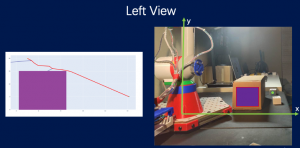
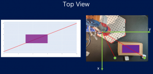 First we see if in the top view(Z-plant), the arm will hit the obstacles. If not, the robot arm could directly go to grap the objects. If did, we will first find the shortest path in Z-plant, and then solve the motion-planning in XY-plant, which is a 2-dimensional problem.
So now we reduce the dimension and make Jacobian Matrix easily to compute. About the specific compuatation, Will introduce it in RRT part.
First we see if in the top view(Z-plant), the arm will hit the obstacles. If not, the robot arm could directly go to grap the objects. If did, we will first find the shortest path in Z-plant, and then solve the motion-planning in XY-plant, which is a 2-dimensional problem.
So now we reduce the dimension and make Jacobian Matrix easily to compute. About the specific compuatation, Will introduce it in RRT part.
Forward Kinematic
DH Table
When we talk about the kineamtic of Robotic Arm, Denavit-Hartenberg(DH) table is important for both Forward Kineamtic and Inverse Kineamtic. DH table is DH-Table is a method which could build the model of the robot arm and get the relationship between different joints.
We could see, based on the different angles of joints(assume the length of arms are fixed), we could get a relationship between the start point(base coordinate) and the terminated point(gripper coordinate).
Now we could see a form of our DH table, which is the model of our robot arm.
This DH table includes 4 parameters: α, a, θ, d, each parameter have different functionality when we model the robot arm.
α:The angle that rotate Z axis by the original X axis.
a: The distance from original Z axis to rotated Z axis following original X axis
θ: The angle that rotate X axis by the rotated Z axis.
d: The distance from original X axis to rotated X axis following rotated Z axis.
So based on this parameter, we could describe a complicated robot arm joint by joint. And then, a DH table function, which is also a matrix, could be compuated:
Which is a single matrix for one joint. We just need multiple different transfer matrix for different joints together.
Based on the DH table and our robotic model, we proposed a DH transfer code for solve the forward problem.
Inverse Kinematic
Jacobian Matrix and Gradient Descent
About the Inverse Kinematic, we will combine Jacobian Matrix and DH table to get the Inverse Kinematic.
the Jacobian Matrix of a vector-valued function in several variables is the matrix of all its first-order partial derivative. With Jacobian Matrix, we could know the gradient direction of a function(in our problem, it is DH table.)
For instance, in our problem, we know we have such a function:
DH(θ), θ = (θ1,θ2,θ3,θ4,θ5,θ6 )
Then, with Jacobian Matrix , we could get a gradient of DH, assume it is: ΔDH
Then we change the value of θ, new θ* = θ – λΔDH, here λ is step.
Then the gradient descent until we find the final answer.
The Jacobian Matrix Code could find in Github.
Dimension Reduction
But here is a problem: the dimension of six-axis is too large. So it is hard to find a DH value to help us do the Jacobian method and gradient descent. To solve this problem, we proposed a method to reduce the dimension and dof, to make computation more cheap.
First we see if in the top view(Z-plant), the arm will hit the obstacles. If not, the robot arm could directly go to grap the objects. If did, we will first find the shortest path in Z-plant, and then solve the motion-planning in XY-plant, which is a 2-dimensional problem.
So now we reduce the dimension and make Jacobian Matrix easily to compute. About the specific compuatation, Will introduce it in RRT part.
kkka d f
In our motion-planning part, we will use RRT to be the basic algorithm, and combined kinematic part to compute a track for our armbot.
For specific code, please see Github
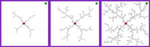 First we see the top view. We will figure out if armbot will go through the obstacles. If it will, we will do RRT in another planet:
 In this planet, we could model the obstacles, and then use RRT to generate a path like above graph shows. And for each point, we need do:
What is RRT?
A rapidly exploring random tree (RRT) is an algorithm designed to efficiently search nonconvex, high-dimensional spaces by randomly building a space-filling tree.
(Figure refer from https://towardsdatascience.com/how-does-a-robot-plan-a-path-in-its-environment-b8e9519c738b)
Generaly understand, RRT is a randomly tree in a enviroment. It will keep growing, and if hit the obstacle, it will change the direction. If RRT algorithm have enough samples in a workspace, it surely could find a safe path in a tree which explore all the sapce in environment. It is the general ideal of RRT. RRT is a highly developed algorithm, so we could directly use it.How to apply RRT?
As we mentioned in Kinematic part, we need reduce dimension first. For instance:
First we see the top view. We will figure out if armbot will go through the obstacles. If it will, we will do RRT in another planet:
In this planet, we could model the obstacles, and then use RRT to generate a path like above graph shows. And for each point, we need do:
- Use Inverse Kinematic to compute the angles of Joints: Tell us how to arrive that position
- Collision Detection: Check if our armbot will hit obstcales in other joints and arms.
In this part, we will acquire the relative 3-dimensional position between the camera and the target box. The raw information that we could utilize includes the RGB picture and the depth picture of the domain.
To achieve such a goal, we need to:
 As from the picture above, two boxes are laying inside the environment. Those pink dots around the margin are generated because of the poor lighting (this picture was taken at night).
We will first turn the image into a greyscale one, then binarilize it and get the following one:
As from the picture above, two boxes are laying inside the environment. Those pink dots around the margin are generated because of the poor lighting (this picture was taken at night).
We will first turn the image into a greyscale one, then binarilize it and get the following one:
 Note that one might need to tune the threshold based on the lighting to get the result of greater quality.
There are lots of ways to segment the two white regions out of the black background. Here we chose a method that utilizes the 4-sided shape of the box.
More precisely, we apply the findContours function in OpenCV to find out all contours within the domain. Then we use the approxPolyDP function to approximate the contours we got previously. This function is an implementation of Douglas-Prucker algorithm.
Then we filter out all contours that have more or less than four sides by simply checking the length of the returned array from the approxPolyDP function.
We finally get the segmented parts by parsing the contours that have four sides.
Note that one might need to tune the threshold based on the lighting to get the result of greater quality.
There are lots of ways to segment the two white regions out of the black background. Here we chose a method that utilizes the 4-sided shape of the box.
More precisely, we apply the findContours function in OpenCV to find out all contours within the domain. Then we use the approxPolyDP function to approximate the contours we got previously. This function is an implementation of Douglas-Prucker algorithm.
Then we filter out all contours that have more or less than four sides by simply checking the length of the returned array from the approxPolyDP function.
We finally get the segmented parts by parsing the contours that have four sides.

 One can of course further optimize the structure to get better results.
 This process is quite straightforward, we parse the part that contains the target box based on the 2-d position information we got from the last section. Then we take an average of the depth within that domain to generate the relative depth between the box and the camera.
 By now, we have acquired all information we need to grab the target box.
-
- Recognize all boxes inside the picture;
- Recognize the digit on each box and pick the target box;
- Get the relative depth position of the box
Multi-object detection
In this section, we will segment the parts that include all the boxes within the domain, from the RGB picture.Typical RGB pictures of boxes in the domain
The binary picture of the environment
The segmented picture
Digit recognition
We use a simple Convolutional Neural Network (CNN) to conduct the digit recognition task.Pre-processing
To improve the success rate of recognition, we first resized the segmented part to 28 by 28 pixels. Then we again binarilize it based on the threshold we used before. The rescaled-binary picture pictures are finally being recognized by the CNN.CNN architecture
Since the task of recognizing digit is comparatively easy, we, therefore, adopt a very basic CNN architecture as follow:The CNN architecture
Training
We use the famous MNIST dataset to train our model. We take 50000 pictures from the training data. For the specific training setting, please refer to our code.Overall pipeline
Since the digits on the boxes are directly from the MNIST dataset, the CNN training process could therefore be offline. Once we get the trained CNN, we will feed the segmented parts that we got from the multi-object detection part into the CNN. We will pick our target digit and extract the in-plane coordinates of its four corners. The 2-d position information (a 4 by 2 array) is then passed to the next step.Depth acquisition
In this section, we will get the depth information of the target box based on the in-plane coordinates and the depth picture of the domain (as follow).The depth picture of the entire domain
The segmented depth picture
- Calibration procedures for all sensors
- Include data sheets
- Experimental procedure
- Preliminary results (tables of raw data)
- Statistical analysis; sample calculations
Design Process and Planning
- Ideation, design alternatives
- Using Open Source from Thingsverse to build a 6-freedom Robot Arm
- Combing Roboting Arm, Camera to complete a gripping work.
- Using Open Source from Thingsverse to build a 6-freedom Robot Arm
- Ranking of ideas
- What ranking system did you use?
- How did you manage your project?
- Who was in charge of what?
- What were all the tasks you identified early on?
- Which ones did you not think about at all? (Save this item for the lessons learned in the Conclusion)

Prototyping
- Parts, Bill of Materials
- Using 3D printing to building the Robot Arm
- Buy a Intel RealSense Camera to be the senser
- Manufacturing processes used
- 3D Print

Testing/Experimentation
- Preliminary results
- Debugging and shake-down of experiment
- Make sure all the systems communicate and work
- Analysis, Discussion
- Your results may not be what you expected
- Consider why this may be the case
- If you are able to get data that can be analyzed rigorously (not expected), what methods would you use to reduce the information into generalizable knowledge?
Conclusion and Future Work
- Lessons learned
- How would you do things differently the next time you design?
- What advice do you have for someone who wants to replicate your project?
- Next steps
- How would you advise the next group of students who take on your project?
- What other types of experiments can now be performed on the same system?