balancePROP
Overview
This project will demonstrate the basic electronics, controls, and programming necessary for Proportional-Integral-Derivative (PID) control of nonlinear dynamic systems. It will use a basic microcontroller to think, an accelerometer to know where it is, and motors to move.
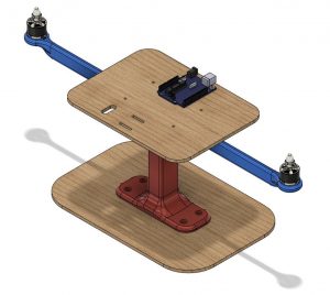
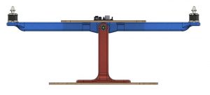
This demonstration consists of a lever with a fulcrum at midspan and two motors attached on either end. The two motors exert vertical thrust forces on either side of the lever, tilting it to one side or the other. The intent is to 1) balance the arm using PID control and 2) have it hold any angle.
Without any feedback or control loops, this nonlinear system will be nearly impossible to balance due to slight dissimilarities between the two sides’ thrusts because of small differences in the friction, motors, length of wires, etc. To truly balance the beam and have it reject disturbances (such as a pencil tap), we need some feedback so that we can adjust how fast the motors spin in real-time.
To provide that feedback, an accelerometer is added to the mix to determine the orientation of gravity. From the measurements of Earth’s gravitational field, we can determine what angle the beam is actually at and how far we are away from where we want it to be. In controls, these values are called: the set-point (where you want to be), the actual (where you are now), and the error (how far away you are). After determining the error from the setpoint, its derivative and integral can be calculated. The value of the error, its integral over time, and its derivative with respect to time can be multiplied by amplification constants, or gains K_p, K_i, and K_d respectively.
For a graphic demonstration of how the system eventually will work, check out the figure below. The setpoint will be an angle, the actual angle will be determined by the accelerometer, and the error is the difference between the actual angle and the setpoint. The “actuating signal” is therefore an angle, but the brushless motors are controlled by pulse-width modulated (PWM) signals (a.k.a. NOT angles). Therefore, the “system” here is a linear transformation from angles to the PWM control signals of the motors.

Materials and Parts
There are two main sub-systems to this project: 1) The balance-beam stand itself and 2) the electronic feedback and control systems.
The beam and stand are constructed mainly of 3D-prints and a couple laser-cut parts. The electronics systems require some solder, wire-stripping, and heat-shrinking but predominantly consist of an Arduino, a gyroscope/accelerometer, two brushless motors, two electronic speed controllers (ESCs), two propellers, a proto-shield, some connectors, and a few jumpers.
Mechanical Fabrication
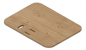
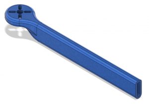
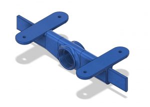
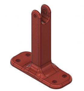
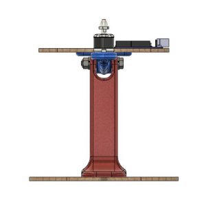
There are four 3D-printed parts which will form most of the structure for this device. There are two identical arms, one arm-pivot, and one fulcrum-stand. Two 608 bearings and four M3 nuts are installed in the arm-pivot and then the arms can be glued and slid onto the arm-pivot. The completed beam assembly can then be bolted to the top of the fulcrum-stand using the 5/16″ bolt, washers, and lock-nut.
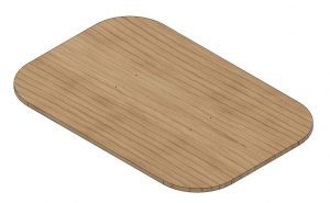
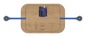
There are two laser-cut pieces that will form as a base and a removable electronics-table. The base is bolted to the bottom of the stand with four M3 screws and the electronics-table can be mounted to the arm-pivot using four more M3 screws.
You have now completed the purely mechanical assembly! Now, we can start mounting the electronics.
The two motors are mounted to their locations at the tips of the arms using eight M3 screws. The ESCs and Arduino can be mounted to the electronics-table with some velcro so that they can be easily moved or removed depending on wire lengths or different set-ups.
That’s all there is to building the device, now let’s start wiring it up and programming it to control itself (and eventually the world -evil laugh-).


Electronic Fabrication
Electronics fabrication for the PID Balance Beam is a little more involved than the mechanical side only. The best place to start is to make sure that your brushless motors have 3.5mm male bullet connectors on all three of their leads and that they have all been properly covered in heat-shrink to remove the possibility for a short. After that, the ESCs, need 3.5mm female bullet connectors on their motor leads, female XT60 connectors on their battery leads, and female DuPont connectors on their signal leads. Remember to put the heat-shrink on the wires first and to situate the heat-shrink as far away from the heat as possible while soldering.
The next step in the process is making a Y-cable to send battery power to the two ESCs. The battery Y-cable should have two male XT60 connectors and one female XT60 connector. LiPo batteries typically come pre-installed with male XT60 connectors.
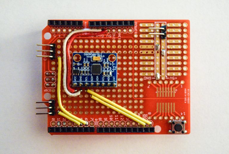
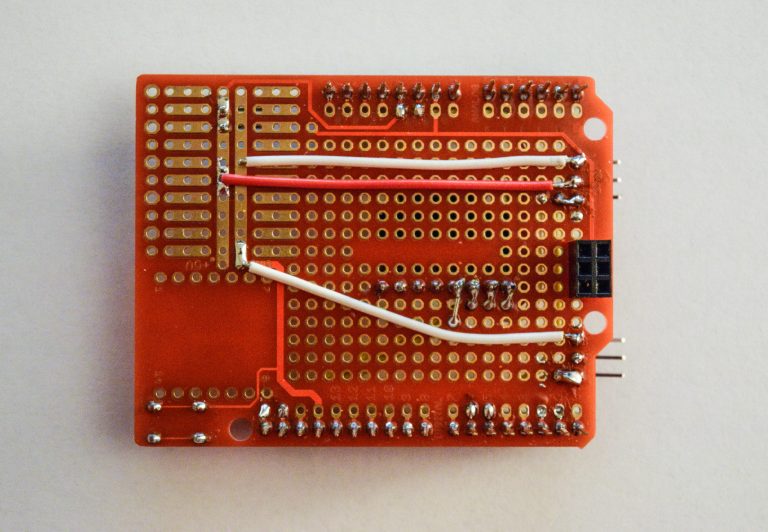
After the Y-cable is finished, the shield can be made for the Arduino. The shield is the most intricate part of the process but is relatively simple, especially with the provided wiring diagram. Begin by soldering the pins and button that came with the shield onto the PCB. In addition to the stock pins and button, nine jumper-wires, eight pin-headers, and one accelerometer/gyroscope needs to be soldered to the proto-shield. Utilize both the front and the back of the proto-shield for easier wire routing and soldering.
Programming
Calculating the angle and writing the PID loops is easier portion of the programming for this project. The part that is less intuitive is initializing and calibrating the ESCs. Just as noted in the last paragraph of the overview, the motors are controlled by the ESCs and the ESCs are controlled using PWM signals. The PWM signals accepted by the ESCs are sent at frequency of 50Hz with a pulse-widths of 1-2 micro-seconds. A 1 micro-second pulse corresponds to minimum throttle and a 2 micro-second pulse to maximum throttle. Before using the ESCs, they need to be initialized and calibrated so that that know what max- and min-throttle are.
The initialization and calibration process is one of the many safety features built in to ESCs. The ESCs will not start-up if they are powered-on with anything but min-throttle applied. This prevents the motors from starting up when your hands are close-by and allows you to establish control before the motors start spinning. To enter the calibration and initialization protocol, max-throttle should be applied to the ESCs upon powering. After holding max-throttle for 2 seconds, min-throttle should be held for 2 seconds, and then the ESC should initialize and beep a number of times (corresponding to the input voltage). The code provided will calibrate the ESCs upon every power-up to give the user a number of seconds to get clear of moving propellers.
Once the ESCs are initialized, the angle can start to be calculated. The gravity of Earth is knows to be 9.8 m/sec^2 downward at its surface. From this information, and by looking at the accelerations in the z- and x-axes and doing a little trigonometry, the tilt can be calculated. Calculating the error and its integral and derivative and plugging those values into the PID loop gives an output. That output is not really usable in this form so it is mapped to the 1-2 micro-second range that the ESCs accept and then sent to the ESCs.
There is some error checking and an integral term cap to make operation more stable and handle some edge-cases that are sure to result in any curious testing. The PWM values are checked to make sure that they are within the accepted ranges and the integral term is examined to make sure that it hasn’t gotten too large. If the PWM error checks are being used, then control is being saturated. This means that the PID loops are either sending min- or max-throttle to the ESCs which will hamper effective control because the ESCS cannot actually deliver what the controller is asking for.
The final little bit of code plots the values of relevant variable in the Arduino serial plotter. This provides a way to characterize how well your controller is tuned and how well it rejects disturbances. The plotted values can be changed if you would like to view other the other attributes of your completed linear control system!
Build Videos and Demonstrations


