armBOT v1.0 under development
A Step Towards Hands-on Collaborative Learning Journey
armBOT Objective
The goal is to equip you with a multitude of skills required to build an interdisciplinary robotics project remotely or in person. You will develop working knowledge in
- Teleoperability,
- Sensors,
- Actuators,
- Simulation through ROS,
- Research methods,
- Technical communication.
armBOT Overview
The armBot has the following capabilities as of the latest version
- 6 DoF arm
- Remotely operated
- Visual object detection
- Open-source collaborative platform

Sensors
To enable the arm with the above mentioned functionality, certain sensors have been used and in this section we will develop an understanding of the working of the sensors and the ways of using them.
MPU 6050

MPU 6050
- 3-axis gyroscope, 3-axis accelerometer
- I2C communication
- 3-5 V power supply
- Arduino Uno/ Nano
- MPU 6050
- Connecting wires
- Anaconda Installation
- Python version >= 3.5
- Jupyter Notebook
- Arduino IDE

28BYJ-48 Stepper Motor

28BYJ-48 Stepper Motor with Motor Controller
- 5 V , rated voltage
- requires external power source for motor driver
- unipolar coil
- 1/64 , gear reduction
- control of multiple motors together
- control of motor remotely using AWS IoT ( or any other service)
- Using ESP32, motor control using a website interface demo
Ultrasonic Sensor

Ultrasonic sensor
- 5 V, rated voltage
- Accuracy = 3 mm
- Practical Measuring Distance = 2 cm to 80 cm
DHT11

DHT11 Temperature and Humidity Sensor
- 3.3 V or 5 V , working voltage
- 20-95% Relative Humidity measurement range
- 0-50℃, temperature measurement range
Subsystem Definition and overview
When the above parts come together, they give rise to silos which play important role in making the armBOT work.
Controlling the robot remotely requires us to use services which can capture our commands, and then at the same time, relay them to the receiver’s end.
The whole process requires :
- hardware to connect to the internet on receiver and transmitter end
- service to allow the hardware to send the commands
You can learn more on the topic by visiting the link here.
Apart from the physical structure, a robot arm comprises of algorithms which actually tells it what to do and how.
Robotic Operating System( ROS) provides us with a set of tools and frameworks to model our test environment and robot in a virtual setting and determine the consequences of different algorithms on the system as per our need.
To get up to speed on ROS from the basics, feel free to browse through the link .
Once you are comfortable with ROS environment, jump on here , to learn on controlling your armBOT using ROS.
In order to make the robot autonomous, we need to make sure it can somehow map the surrounding space. One way of doing so it equipping it with vision capabilities and a camera can be used for our case in armBOT.
The field of AI which allows the algorithms to identify/detect the obejcts is called computer vision (CV). Click here, to get started with CV examples.
You might wish to install the required softwares like Anaconda before starting. Learn more about the steps, here, under the “Machine Learning tab”.
Till now we mostly discussed about the software side of the work. But to move the robot physically, we would need small computers which can take the sensor data, do limited processing( wherever required), and relay the output to the sensors and actuators based on the code.
In armBOT v1.0 and v1.1, the primary microcontroller used has been Arduino Uno. To get started with it, kindly follow the exercises and example using alphaBOT, here.
Other microcontrollers used or of consideration are:
- ESP8266
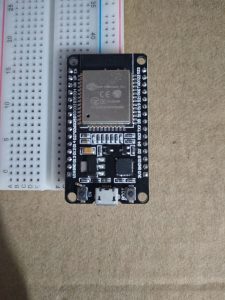
- ESP32
- Particle Argon and Xenon
Learn more about them, here.


Author information
This page is made by Ravi Prakash in Fall 2020. A Master of Science student in the Thomas Lord Department of Mechanical Engineering and Materials Science. For further questions or advice, please contact professor George Delagrammatikas: gd87@duke.edu