3D Printing
Microcontrollers
Robotics/AI
3D Printing


As part of the master’s program in MEMS, students are required to purchase a 3D printer kit, assemble it at home, and use it to perform their projects. These printers generally cost less that $200 USD and can produce very high quality prints once calibrated properly.
This calibration process is part of the the hands-on training students are immersed in that teaches them critical skills in problem-solving and troubleshooting, as they actively reinforce the content knowledge from their mechanical, electrical, and programming courses.
Starting Summer 2020, the printer of choice for this course is the Creality Ender 3 which can be found here. There are vast online resources that will help you through the ‘build, calibrate, design, and implement’ process that will make your 3D printer a critical part of your required design and prototyping training. We recommend that you visit the links below before embarking on your 3D printer journey or deciding on a CAD program or slicer software to use.
- Complete Beginner’s Guide
- First 7 Projects
- Interested in 24 Upgrades?
- Ender 3 Vent Ring
- Extruder Motor Knob
- Fan Cover
- Spring Tensioner
- Cable Clips
- Filament Guide
- Print Quality Troubleshooting
- Slicer Calibration
- CAD: Using Onshape Playlist
- Slicer: Using Cura
- Free STL files
- Advanced
Here provides three basic samples for 3D printing.
Microcontrollers


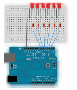
Write the code to blink 6 LEDs attached to the Arduino by using a for() loop to cycle back and forth through digital pins 2-7.
The LEDS are turned on and off, in sequence, by using both the digitalWrite() and delay() functions.
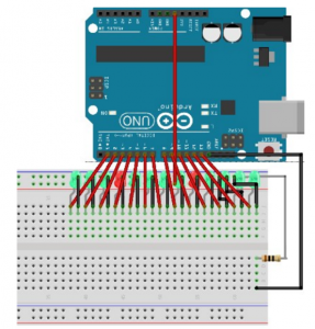
Write a code to turn on each LED in turn. (Use max 14 LED. The solutions is for 14 LED.)
Use while loop to calibrate the value of an analog sensor.

While a button attached to digital pin 2 is pressed, the program runs a method called calibrate() that looks for the highest and lowest values of the analog sensor. When you release the button, the sketch continues with the main loop.(You need to write the calibrate yourself.)
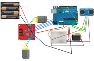
Setup for pins >> Serial connection >> Rotate the motors in 4 directions
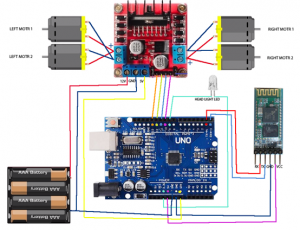
First, you need to include  and  library.

Then define the sensor pings and design the reaction of the car to obstacle (for example, go back, look right, look left, and go to the clear area.) Lastly, Design the path if both sides are clear.
First, calibrate the accelerometer: Read the value from x, y and z in mV when there are no inputs. This is the zero g (9.8m/s^2) reading for each pin.
Given that the accelerometer has sensitivity of 330mV/g, come up with the conversion to real acceleration.
Print the results.

int timer = 100; // The higher the number, the slower the timing.

void setup() {

// use a for loop to initialize each pin as an output:

for (int thisPin = 2; thisPin < 8; thisPin++) {

pinMode(thisPin, OUTPUT);

}
}

void loop() {

// loop from the lowest pin to the highest:

for (int thisPin = 2; thisPin < 8; thisPin++) { // turn the pin on: digitalWrite(thisPin, HIGH); delay(timer); // turn the pin off: digitalWrite(thisPin, LOW); } // loop from the highest pin to the lowest: for (int thisPin = 7; thisPin >= 2; thisPin--) {

// turn the pin on:

digitalWrite(thisPin, HIGH);

delay(timer);

// turn the pin off:

digitalWrite(thisPin, LOW);

}
} Void setup(){
for(int i=1; i<14; i=i+1){
pinmode(i,output);
}
}
Void loop(){
for(int i=1; i<14; i=i+1){
digitalWrite(i,HIGH);
delay(200);
digitalWrite(i,low);
}
}
const int sensorPin = A0; // pin that the sensor is attached to

const int ledPin = 9; // pin that the LED is attached to

const int indicatorLedPin = 13; // pin that the built-in LED is attached to

const int buttonPin = 2; // pin that the button is attached to

// These variables will change:
int sensorMin = 1023; // minimum sensor value
int sensorMax = 0; // maximum sensor value
int sensorValue = 0; // the sensor value

void setup() {

// set the LED pins as outputs and the switch pin as input:

pinMode(indicatorLedPin, OUTPUT);

pinMode(ledPin, OUTPUT);

pinMode(buttonPin, INPUT);
}

void loop() {

// while the button is pressed, take calibration readings:

while (digitalRead(buttonPin) == HIGH) {

calibrate();

}

// signal the end of the calibration period

digitalWrite(indicatorLedPin, LOW);

// read the sensor:

sensorValue = analogRead(sensorPin);

// apply the calibration to the sensor reading

sensorValue = map(sensorValue, sensorMin, sensorMax, 0, 255);

// in case the sensor value is outside the range seen during calibration

sensorValue = constrain(sensorValue, 0, 255);

// fade the LED using the calibrated value:

analogWrite(ledPin, sensorValue);
}

void calibrate() {

// turn on the indicator LED to indicate that calibration is happening:

digitalWrite(indicatorLedPin, HIGH);

// read the sensor:

sensorValue = analogRead(sensorPin);

// record the maximum sensor value

if (sensorValue > sensorMax) {

sensorMax = sensorValue;

}

// record the minimum sensor value

if (sensorValue < sensorMin) {

sensorMin = sensorValue;

}
} char t;
void setup() {
pinMode(13,OUTPUT); //left motors forward
pinMode(12,OUTPUT); //left motors reverse
pinMode(11,OUTPUT); //right motors forward
pinMode(10,OUTPUT); //right motors reverse
pinMode(9,OUTPUT); //Led
Serial.begin(9600);
}
void loop() {
if(Serial.available()){
t = Serial.read();
Serial.println(t);
}
if(t == 'F'){ //move forward(all motors rotate in forward direction)
digitalWrite(13,HIGH);
digitalWrite(11,HIGH);
}
else if(t == 'B'){ //move reverse (all motors rotate in reverse direction)
digitalWrite(12,HIGH);
digitalWrite(10,HIGH);
}
else if(t == 'L'){ //turn right (left side motors rotate in forward direction, right side motors doesn't rotate)
digitalWrite(11,HIGH);
}
else if(t == 'R'){ //turn left (right side motors rotate in forward direction, left side motors doesn't rotate)
digitalWrite(13,HIGH);
}
else if(t == 'W'){ //turn led on or off)
digitalWrite(9,HIGH);
}
else if(t == 'w'){
digitalWrite(9,LOW);
}
else if(t == 'S'){ //STOP (all motors stop)
digitalWrite(13,LOW);
digitalWrite(12,LOW);
digitalWrite(11,LOW);
digitalWrite(10,LOW);
}
delay(100);
} #include //standard library for the servo
#include //for the Ultrasonic sensor function library.
//L298N motor control pins
const int LeftMotorForward = 6;
const int LeftMotorBackward = 7;
const int RightMotorForward = 5;
const int RightMotorBackward = 4;
//sensor pins
#define trig_pin A1 //analog input 1
#define echo_pin A2 //analog input 2
#define maximum_distance 200
boolean goesForward = false;
int distance = 100;
NewPing sonar(trig_pin, echo_pin, maximum_distance); //sensor function
Servo servo_motor;
void setup(){
pinMode(RightMotorForward, OUTPUT);
pinMode(LeftMotorForward, OUTPUT);
pinMode(LeftMotorBackward, OUTPUT);
pinMode(RightMotorBackward, OUTPUT);
servo_motor.attach(9); //our servo pin
servo_motor.write(115);
delay(2000);
distance = readPing();
delay(100);
distance = readPing();
delay(100);
distance = readPing();
delay(100);
distance = readPing();
delay(100);
}
void loop(){
int distanceRight = 0;
int distanceLeft = 0;
delay(50);
if (distance <= 20){ moveStop(); delay(300); moveBackward(); delay(400); moveStop(); delay(300); distanceRight = lookRight(); delay(300); distanceLeft = lookLeft(); delay(300); if (distance >= distanceLeft){
turnRight();
moveStop();
}
else{
turnLeft();
moveStop();
}
}
else{
moveForward();
}
distance = readPing();
}
int lookRight(){
servo_motor.write(50);
delay(500);
int distance = readPing();
delay(100);
servo_motor.write(115);
return distance;
}
int lookLeft(){
servo_motor.write(170);
delay(500);
int distance = readPing();
delay(100);
servo_motor.write(115);
return distance;
delay(100);
}
int readPing(){
delay(70);
int cm = sonar.ping_cm();
if (cm==0){
cm=250;
}
return cm;
}
void moveStop(){
digitalWrite(RightMotorForward, LOW);
digitalWrite(LeftMotorForward, LOW);
digitalWrite(RightMotorBackward, LOW);
digitalWrite(LeftMotorBackward, LOW);
}
void moveForward(){
if(!goesForward){
goesForward=true;
digitalWrite(LeftMotorForward, HIGH);
digitalWrite(RightMotorForward, HIGH);
digitalWrite(LeftMotorBackward, LOW);
digitalWrite(RightMotorBackward, LOW);
}
}
void moveBackward(){
goesForward=false;
digitalWrite(LeftMotorBackward, HIGH);
digitalWrite(RightMotorBackward, HIGH);
digitalWrite(LeftMotorForward, LOW);
digitalWrite(RightMotorForward, LOW);
}
void turnRight(){
digitalWrite(LeftMotorForward, HIGH);
digitalWrite(RightMotorBackward, HIGH);
digitalWrite(LeftMotorBackward, LOW);
digitalWrite(RightMotorForward, LOW);
delay(500);
digitalWrite(LeftMotorForward, HIGH);
digitalWrite(RightMotorForward, HIGH);
digitalWrite(LeftMotorBackward, LOW);
digitalWrite(RightMotorBackward, LOW);
}
void turnLeft(){
digitalWrite(LeftMotorBackward, HIGH);
digitalWrite(RightMotorForward, HIGH);
digitalWrite(LeftMotorForward, LOW);
digitalWrite(RightMotorBackward, LOW);
delay(500);
digitalWrite(LeftMotorForward, HIGH);
digitalWrite(RightMotorForward, HIGH);
digitalWrite(LeftMotorBackward, LOW);
digitalWrite(RightMotorBackward, LOW);
} const int xpin = A0; // x-axis of the accelerometer
const int ypin = A1; // y-axis
const int zpin = A2; // z-axis
void setup() {
// put your setup code here, to run once:
Serial.begin(9600);
}
void loop() {
// put your main code here, to run repeatedly:
int x = analogRead(xpin); //read from xpin
delay(1); //
int y = analogRead(ypin); //read from ypin
delay(1);
int z = analogRead(zpin); //read from zpin
Serial.print(((float)x-344)/330*9.8);
Serial.print(((float)y-410)/330*9.8);
Serial.print(((float)z-340)/330*9.8);
delay(1000);
} Robotics/AI


Using ROS to control a complicated robotic arm is commonly seen in the real industry now. Learn how to how to simulate the armBOT and do the motion planning for it in ROS by clicking here.
Tutorial for downloading tensorflow based on python.
- Download Anaconda
- In the command window, input conda–version. Getting the corresponding version number means successful installation
- Run anaconda prompt and input”conda create -n tensorflow python=3.5.2″
- Input “activate tensorflow”
- Input “pip install -i https://pypi.tuna.tsinghua.edu.cn/simple/ https://mirrors.tuna.tsinghua.edu.cn/tensorflow/windows/cpu/tensorflow-1.1.0-cp35-cp35m-win_amd64.whl”
Tutorial for downloading OpenCV for python.
- Download Anaconda
- Download opencv_python
- Run anaconda prompt and input “pip install opencv_python-3.4.5-cp37-cp37m-win_amd64.whl”
- Easy Sample
- Corresponding Picture

