

Deciphering the Arduino and Motor Driver
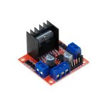
The Arduino is the decision-making unit of our robot and it is required to understand its functioning. This section provides insight into the basic outlay of the device and also discusses the various applications the Arduino could be used for with suitable examples. The working principle of the motor driver L298N is also viewed.

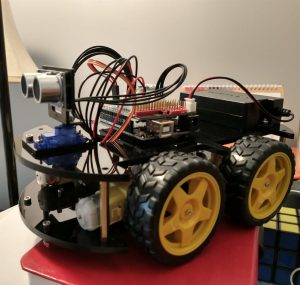
This section elaborates on the blueprint of the robot’s design. Considerations are made in terms of choosing the right shape of the body, as well as providing adequate space to mount the electronic components. The schematic diagram of how the electronic items need to be connected together is also presented here.


(De)coding the MPU6050 and the Control action
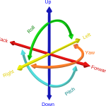
The information provided by the MPU6050 about the change in the angular position of the robot is valuable for the Arduino to decide what the necessary action is to restore balance. In this section, a comprehensive understanding of MPU6050’s working is made and we discuss how to use the Arduino IDE to code out and retrieve the data from the sensor. We also look into the Proportional-Integral-Derivative (PID) Control and incorporate its usage in our system.

Given the availability of a variety of mobile robots, the concept of balancing should be extended to each kind, be it legged or wheeled. The method used to introduce balancing intuitively differs from robot to robot. We look into ways by which today’s industries make state-of-the-art robots that are smart enough to not just balance, but also perform other movement-related tasks.
Gesture-Controlled Semi-Autonomous Vehicle
In this section, a different project idea based on controlling a robot’s motion using hand gestures is explored. Discussion is done on the motivation of the concept, the parts required and the methodology adopted to execute gesture control on a 4 – wheeled mobile robot.