This project is using Robot Operation System to control motion of real 6-dof robot arm. In this page, you are able to learn how to use Arduino to control the motion of a robot arm, how to do path planning by using ROS and how to set up communication between ROS and Arduino.
The hole system decomposition of the big project is shown as follow. My part is represented by pink color. If you want to learn more about the computer vision part or Gazebo simulation part, which represented by Green and Blue color, you can visit the other two member’s personal page.

Figure 1. System decomposition
Hardware:
Jetson Nano is used to run ROS, deep learning and depth camera in this project. It is a small, powerful computer designed to power entry-level edge AI applications and devices.

Figure2. Jetson Nano 2GB
Arduino UNO is mainly used to do the base control part. Comparing to other microcontrollers, Arduino is easy and convenient to use. With plentiful open source code and tutorial video online, it is the best choice for beginner or for prototype building.

Figure3. Arduino
The Tic T500 USB Multi-Interface Stepper Motor Controller makes basic control of a stepper motor easy, with quick configuration over USB using their free software. The controller supports six control interfaces: USB, TTL serial, I²C, analog voltage (potentiometer), quadrature encoder, and hobby radio control (RC).

Figure4. Tic 500 Motor Controller
In this project, we used the armbot which has been built in capstone previous project. It uses planetary gear and able to hold the position when the power is off.

Figure5. armbot
Software:

Figure 6. ROS melodic
The open-source Arduino Software (IDE) makes it easy to write code and upload it to the board. This software can be used with any Arduino board. The tutorial of how to install the Arduino IDE on Linux is here.

Figure7. Arduino IDE
In my project, the ROS version is Melodic and the system is based on Jestson Nano 2GB. The control part is based on Arduino and TIC500 motor driver.
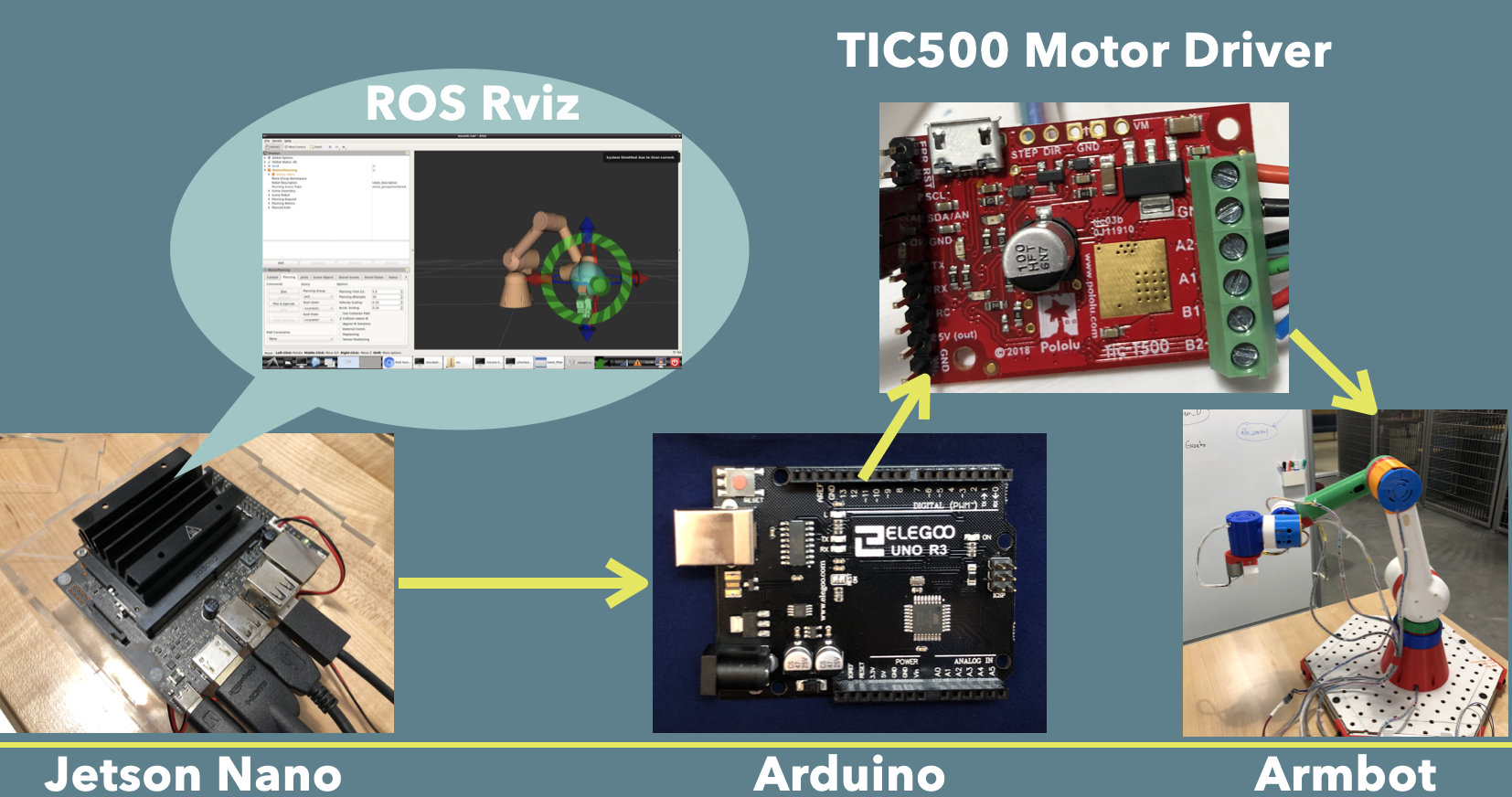
Figure 8. hardware workflow
The workflow of the project is as follow. ROS moveit will help us do inverse kinematics coculation, collision checking and path planning. We can easily use moveit and plan the path through RVIZ interface. After path planning, moveit will publish joint_state topic which is sequence of radian of joints. We can use arduino as a node to subscribe these massage through ros serial. Then, after the ratio transform of radian to angle and planetary gear (which is 38.4:1 ), Arduino will according control the motion of each motor and execute the planned trajectory.
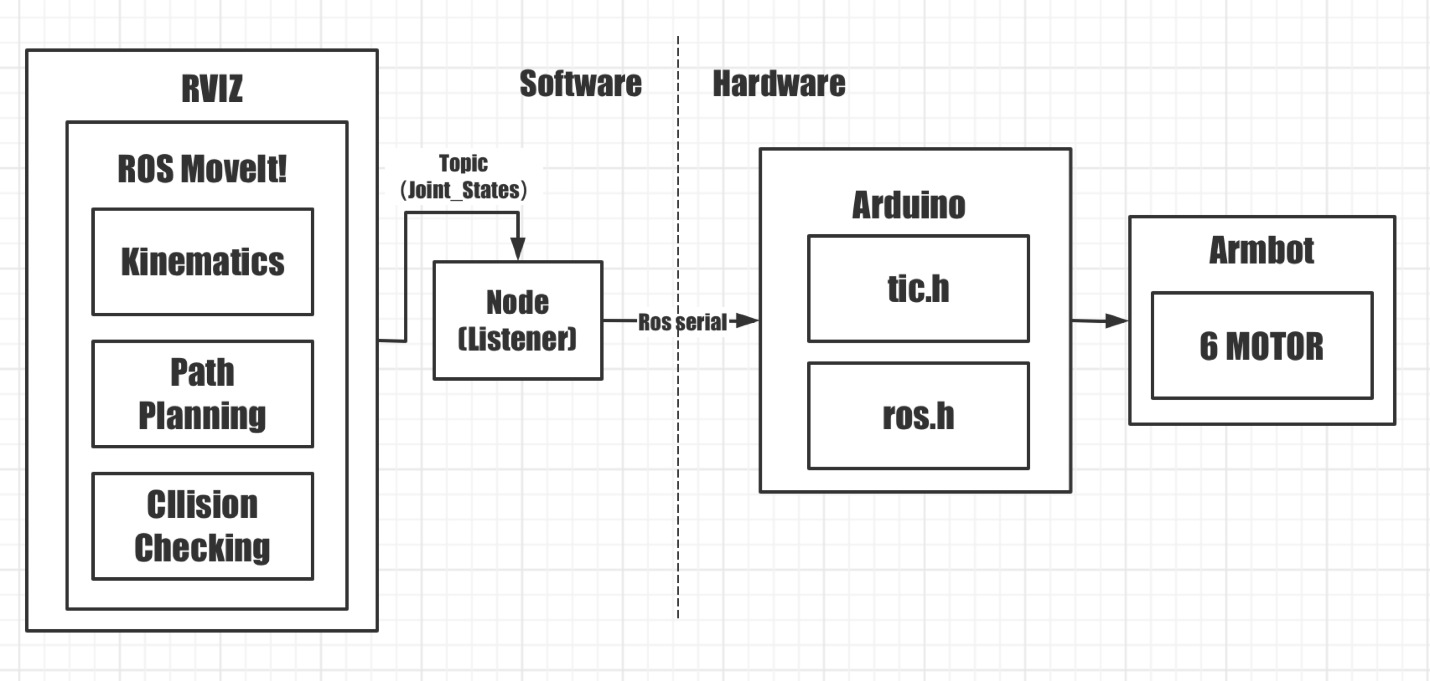
Figure 9. software workflow
We have talked about how to control the motion of armbot from the Step1. But it can only control the robot arm move to programmed position. It will be much better if the robot arm can execute some trajectory automatically instead of setting position by ourselves. Therefore, next step we are going to learn how to use ROS to do the path planning and let the armbot follow this path. You may feel lost like I was when thinking about how to use ROS do the path planning, how can we know the position of each joint and how to send the joint position to Arduino and let it execute. But don’t worry it just need some time to learn step by step. Let figure out how to use ROS to get planned path first.
To do path planning on Moveit, we need to know what is URDF file and robot configuration file. URDF file is an xml file format used in ROS to describe all elements of a robot. We need the robot URDF file to build robot configuration file by using Moveit setup assistant. The robot configuration file contains all necessary files for moveit and path planning in Rviz. After that, we can do path planning in Rviz. Luckily, these knowledges and tutorial are well explained in capstone previous project in this page. The armbot URDF file is here.
Kinematics is used to set up the relationship between robot arm joint coordinates and its spatial layout. There are forward kinematics and inverse kinematics. So, the forward kinematics is to calculate the end effector position from each angle of the joints and inverse kinematics is to calculate the angle of each joint from the position of robot end effector. In the Moveit setup assistant, we used kdl_kinematics_plugin to solve inverse kinematic. In this project, the initial robot arm pose is set in the way shown as follow:
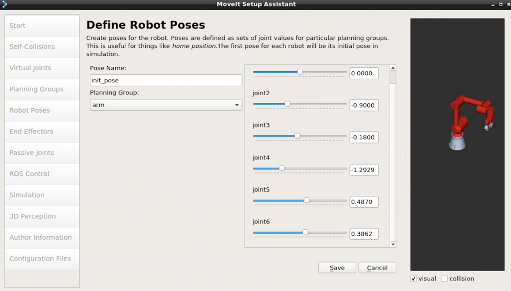
Figure 10. initial robot poses
1.ROS Node:
Node is kind of executable program, and it is a sub-part of your robot system. Every node has its specific jobs and they communicate with each other to satisfied your robot application.
When we are running Moveit to do the path planning, the executing nodes and their relations are shown in picture below.

Figure 11. nodes and their relation in Moveit
2. ROS Message:
ROS message includes topic, service and action to transfer information between nodes.
/joint_states topic is senser message. It contains position information. So, if we can send the position of each joint to Arduino, theoretically, we can set this joint states as aim position of each joint and make the robot arm execute the planned path.

Figure 12. data structure of JointState message

Figure 13. the message in JointState topic
Here are some useful commands you might need:
List all the topic:
rostopic list
Show the message that publishing on the topic:
rostopic echo
Check the message type:
rostopic type
Check the data structure of message:
rosmsg show
1. Install rosserial in ROS
sudo apt-get install ros–rosserial
sudo apt-get install ros–rosserial-arduino
2.Install the ros_libe package in Arduino IDE.
Navigate to Sketch>Include Library> Manage Library and search rosserial package. After installation, the example code can be found from File>Examples>RosserialArduino Library
This part shows how to publish simple topic on ROS and how to use arduino to subscribe this message and accordingly control the motion of motor.
The code is modified according to this tutorial. A subscriber named led_subscriber subscribes to the toggle_led topic which gets and std_msgs::UInt16 data type.
Once the code is uploaded, run the command below step by step:
1.Start the ROS Master
roscore
2.Set up communication
rosrun rosserial_python serial_node.py /dev/tty<USB# or ACM#>
(The serial port can be found from arduino>Tools>port)
3.Publish data
rostopic pub toggle_led std_msgs/UInt16 “data: 100”
“data:100” means the position message is stoned in ‘data’ and the target position for motor is 100. (Note: Don’t confused by the name toggle_led or led subscriber. If you followed this tutorial, you would know I just use its method to control one single motor.
The video below shows the effect:
Code:
#include
#include <std_msgs/UInt16.h>
#include
TicI2C tic;
ros::NodeHandle node_handle;
std_msgs::UInt16 led_msg;void subscriberCallback(const std_msgs::UInt16& led_msg) {
digitalWrite(LED_BUILTIN, HIGH);
tic.setTargetPosition(led_msg.data);
//digitalWrite(LED_BUILTIN, LOW);
waitForPosition(led_msg.data);
//tic.haltAndSetPosition(led_msg.data);}
ros::Subscriber led_subscriber(“toggle_led”, &subscriberCallback);
void setup()
{
pinMode(LED_BUILTIN, OUTPUT);
Wire.begin();
delay(20);
tic.haltAndSetPosition(0);
tic.exitSafeStart();node_handle.initNode();
node_handle.subscribe(led_subscriber);
}void resetCommandTimeout()
{
tic.resetCommandTimeout();
}void delayWhileResettingCommandTimeout(uint32_t ms)
{
uint32_t start = millis();
do
{
resetCommandTimeout();
} while ((uint32_t)(millis() – start) <= ms);
}void waitForPosition(int32_t targetPosition)
{
do
{
resetCommandTimeout();
} while (tic.getCurrentPosition() != targetPosition);
}void loop()
{
node_handle.spinOnce();delay(1);
}
The arduino code for communication between Moveit and Arduino is a little bit complicated. First, it based on the control code for 6 motors of armbot. And we need to convert the joint state message which is radian to angle and then convert the angle according to the gear ratio. It is worth mention that the armbot uses different kind of step motor and the angle it moves for one pulse is different. The hole transformation process is shown in the code void writeStepper() part. The reference resource for this part is here.
After upload the code to arduino, run the command below which is the same with Simple Communication example:
1.Open Rviz
source ~/catkin_ws/devel/setup.bash
roslaunch [your configuration package name] demo.launch
2.Start the ROS Master
roscore
3.Set up communication
rosrun rosserial_python serial_node.py /dev/tty<USB# or ACM#>
(The serial port can be found from arduino>Tools>port)
Then, if the communication has set up successfully, it should look like the following picture.

Code:
#include
//#include <std_msgs/Float64.h>
#include <std_msgs/Int16.h>
#include <std_msgs/UInt16.h>
#include <std_msgs/Int32.h>
#include <sensor_msgs/JointState.h>
#includeTicI2C tic1(16);
TicI2C tic2(15);
TicI2C tic3(14);
TicI2C tic4(17);
TicI2C tic5(18);
TicI2C tic6(19);
int target_angle1;
int target_angle2;
int target_angle3;
int target_angle4;
int target_angle5;
int target_angle6;int joint_status=0;
float TARGET_JOINT_POSITIONS[6] = {0,0,0,0,0,0};
ros::NodeHandle node_handle;
void writeStepper() {
//convert joint state values to degreestarget_angle1 = TARGET_JOINT_POSITIONS[0]*(180/3.14)*21.33;
target_angle2 = TARGET_JOINT_POSITIONS[1]*(180/3.14)*21.33;
target_angle3 = TARGET_JOINT_POSITIONS[2]*(180/3.14)*21.33;
target_angle4 = TARGET_JOINT_POSITIONS[3]*(180/3.14)*5.12;
target_angle5 = TARGET_JOINT_POSITIONS[4]*(180/3.14)*5.12;
target_angle6 = TARGET_JOINT_POSITIONS[5]*(180/3.14)*5.12;tic1.setTargetPosition(target_angle1); //change here
tic2.setTargetPosition(target_angle2);
tic3.setTargetPosition(target_angle3);
tic4.setTargetPosition(target_angle4);
tic5.setTargetPosition(target_angle5);
tic6.setTargetPosition(target_angle6);
waitForPosition1(target_angle1);
waitForPosition2(target_angle2);
waitForPosition3(target_angle3);
waitForPosition4(target_angle4);
waitForPosition5(target_angle5);
waitForPosition6(target_angle6);
node_handle.spinOnce();
}void stepperControlSubscriberCallbackJointState(const sensor_msgs::JointState& msg) {
joint_status=1;
digitalWrite(LED_BUILTIN, HIGH);
TARGET_JOINT_POSITIONS[0] = msg.position[0];
TARGET_JOINT_POSITIONS[1] = msg.position[1];
TARGET_JOINT_POSITIONS[2] = msg.position[2];
TARGET_JOINT_POSITIONS[3] = msg.position[3];
TARGET_JOINT_POSITIONS[4] = msg.position[4];
TARGET_JOINT_POSITIONS[5] = msg.position[5];// Call the method to write the joint positions to the servo motors
writeStepper();}
void resetCommandTimeout()
{
tic1.resetCommandTimeout();
tic2.resetCommandTimeout();
tic3.resetCommandTimeout();
tic4.resetCommandTimeout();
tic5.resetCommandTimeout();
tic6.resetCommandTimeout();
}void delayWhileResettingCommandTimeout(uint32_t ms)
{
uint32_t start = millis();
do
{
resetCommandTimeout();
} while ((uint32_t)(millis() – start) <= ms);
}void waitForPosition1(int32_t targetPosition)
{
do
{
resetCommandTimeout();
} while (tic1.getCurrentPosition() != targetPosition);}
void waitForPosition2(int32_t targetPosition)
{
do
{
resetCommandTimeout();
} while (tic2.getCurrentPosition() != targetPosition);}
void waitForPosition3(int32_t targetPosition)
{
do
{
resetCommandTimeout();
} while (tic3.getCurrentPosition() != targetPosition);}
void waitForPosition4(int32_t targetPosition)
{
do
{
resetCommandTimeout();
} while (tic4.getCurrentPosition() != targetPosition);}
void waitForPosition5(int32_t targetPosition)
{
do
{
resetCommandTimeout();
} while (tic5.getCurrentPosition() != targetPosition);}
void waitForPosition6(int32_t targetPosition)
{
do
{
resetCommandTimeout();
} while (tic6.getCurrentPosition() != targetPosition);}
ros::Subscriber stepper_control_subscriber_joint_state(“joint_states”, stepperControlSubscriberCallbackJointState);void setup() {
pinMode(LED_BUILTIN, OUTPUT);
// Set up I2C.
Wire.begin();
delay(20);tic1.haltAndSetPosition(0);
tic2.haltAndSetPosition(0);
tic3.haltAndSetPosition(0);
tic4.haltAndSetPosition(0);
tic5.haltAndSetPosition(0);
tic6.haltAndSetPosition(0);tic1.exitSafeStart();
tic2.exitSafeStart();
tic3.exitSafeStart();
tic4.exitSafeStart();
tic5.exitSafeStart();
tic6.exitSafeStart();// Set the communication BaudRate and start the node
node_handle.initNode();
node_handle.subscribe(stepper_control_subscriber_joint_state);
}void loop() {
// if(joint_status==1)
// { digitalWrite(LED_BUILTIN, HIGH);
// writeStepper();
//}
// Keep calling the spinOnce() method in this infinite loop to stay tightly coupled with the ROS Serial
node_handle.spinOnce();
delay(200);
}
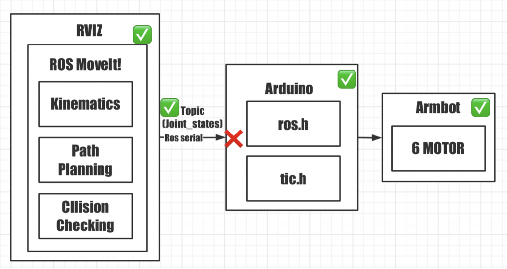
In conclusion, the aim of this project is to use ROS to do the path planning, then send joint state to arduino through ros serial and finally let arduino to do the base control of motor, but I haven’t achieved this goal successfully. As shown in picture below, I have done the path planning and able to subscribe the Joint_states topic by the Arduino node. Also, the base control part in arduino is finished. However, for some reason, the arduino can’t execute the message in the joint_states topic which it has subscribed. One reason for this is that the joint_state is the sensor massage in the Rviz simulation environment, which is using a fake controller. So, maybe we need to learn to use the hardware interface in ros, although the joint_states message already contains the position information we need.