Compressible Flow
Abstract
- This experiment is set up for mechanical engineering students at undergraduate level and helps them to learn analytical, computational and experimental techniques of gas dynamics. As a complementary and advanced lab class, it will teach students who have taken ME 336 more fundamental concepts in compressible flow, as well as developing the ability to solve basic problems about air flowing. In order to let students clearly observe the change of compressible flow, we will measure the pressure at eight same-distance points on the nozzle, when air goes through it. Toward the end of the lab, the students will be required to use collected data to calculate the relation between the size of hole and pressure, so that they can compare variable equations got from the lab to theoretical equations. Through this lab, students are able to understand theoretical equations and use them to compressible flow problems. This paper address the process and techniques used to conduct this type of experiment.
Introduction
- Background/Motivation
- In ME 336L Fluid Mechanics, Thank goals of this class are to understand, analyze and calculate the important properties in fluid dynamics through doing five experiments. As we know, the principle of fluid dynamics is to study the movement of liquids and gases. However, these experiments only cover liquid(water), rather than both liquid and air. Air dynamics also has similar properties with the movement of liquid but it still has a little differences from movement of liquid. This difference is compressibility. Usually, we consider liquid is incompressible, so the questions about fluid dynamics in liquid are comparatively simple and suitable for undergraduate students. Since the problems of air dynamics are always concerned with compressible and incompressible conditions, the study of air dynamics becomes complex and difficult. In order to let students who take this class have a comprehensive study on fluid dynamics, we add a lab about compressible flow into undergraduate curriculum. Professor Nico Hotz and Professor George Delagrammatikas also consider compressible flow is one of significant and interesting topics in fluid mechanics. Existing lab courses are too monotonic, but if adding a lab about air dynamics, like compressible flow, it will enrich the context of the class and give student a new sight to fluid mechanics
- Theory
- Here are some recommended peer-reviewed references:
-
- Lab Development for Fundamental Combustion and Compressible Flow
- Modeling Compressible Air Flow in A Charging or Discharging Vessel and Assessment of Polytropic Exponent
- A Fluid Mechanics Laboratory Nozzle Design Experience
- A New Approach to Teaching Compressible Flow
- A Versatile Compressible Fluid Experiment
- Desgin and Manufacturing of Nozzles and Airfoil Shapes for Compressible Flow Visualizations in a New Engineering Course
- Improving Teaching Technique for Outcome Based Fluid Mechanics Course at Aamu
- A Simple Educational Wind Tunnel Setup for Visualization of Duct Flow Streamlines and Nozzle/Diffuser Boundary Layer Separation
- Assessments of Ultra-Low-Cost Venturi Nozzle in Undergraduate Engineering Classes
- Bringing Research and New Technology into The Undergraduate Curriculum: A Course in Computational Fluid Dynamics
-
- In this experiment, we can specialize compressible flow into nozzle flow. For future works, we can change the observed device(nozzle) to do other topics, like expansion waves, acoustic wave motion, etc. Before running the experiment, we need to know some basic concepts and equations about compressible flow. First, we need to calculate Mach number to check the stage of flow according to velocity the pump provides,
- Ma = V/a = local velocity/speed of sound
- According to Mach number, we can check the stage of flow based on the lists below:
- Ma<0.3 Subsonic&incompressible
- 0.3<Ma<0.8 Subsonic&compressible
- 0.8<Ma<1.2 Transonic(mixed subsonic and sonic flow)
- 1.2<Ma<3.0 Supersonic
- 3.0<Ma Hypersonic
- When air goes through nozzle, pressure and velocity of air will vary corresponding to the shape of nozzle. We use differential pressure manometer to record pressure difference at six points. Then, in order to let students calculate easily, we assume that this is isentropic process and the relation with pressure, density and Mach number is shown as the equation below:

- Through isentropic flow equation, we can get unknown density and Mach number at each point. Then substitute these variables into continuity equation to obtain flow velocity at each point,

- A nozzle is a device which increase or decrease the velocity of air on account of pressure change as well as enthalpy change. Our nozzle have converging and diverging functions, so we introduce both functions from converging nozzle to diverging nozzle.
- Problem Formulation
- The goal of overall design is to learn how air is compressed in the nozzle and how relative variables change in compressible flow through measuring pressure difference in the nozzle. To achieve this goal, we have to pay attention to two sections, assembling and running the experiment. When we assemble this project, we must completely seal the connective parts, in order to diminish energy loss in the flow. Furthermore, since the nozzle has drag coefficient, we have to reduce the drag effect on the flow through keeping the pump and the nozzle in a horizontal line. During the experiment, we need to keep room temperature, pressure and flow rate constant, so that we can assume this experiment is isentropic process. The size of the nozzle is relatively small, so when we measure pressure at five points in the nozzle, pressure difference will be slight between two adjacent points, except the pressure at the throat. However, difficultly controlling isentropic conditions and tiny pressure difference cause actual results have some errors or deviations from theoretical calculations.
Design Process and Planning
- Ideation, design alternatives
- Design No.1: A moveable station to perform compressible flow
- 1. Use aluminum bars to form a two-layer tower with a H-shape base and omni-directional wheels
- 2. Fix air tank on the base
- 3. Fix a thermocouple and a pressure gauge on the tank
- 4. Place a nozzle on the second layer
- 5. Use a U-shape copper tube to connect the tank with inlet of the nozzle
- 6. Connect a long copper tuber with outlet of the nozzle
-
- Design No.2: A portable equipment to perform compressible flow
- 1. Place a pump and a nozzle on the supports
- 2. Insert a flow straightener between the pump and the nozzle
- 3. Seal the joints with tube fitting gaskets and O-rings
- 4. Insert barbed hose fittings into the holes on the nozzle
- 5. Connect differential pressure manometer with the nozzle through barbed hose fittings
- 6. Insert a removable thermocouple into barbed hose fittings to measure temperature
- Ranking of ideas
- We adopt Design No.2
- Advantages:
- 1. Easy to move and handle
- 2. low cost
- 3. Occupy small space
- Disadvantage:
- 1. air power from the pump is not strong as from air tank
- Task management:
- Yeguang Zhou: Mechanical design/Electronics/website
- Yuhan Wang: Mechanical design/CAD
Prototyping
- Parts, Bill of Materials
- Make sure you use a system schematic to label the parts you purchased/procured
- Arduino UNO R3
- Air Dream Replacement Inflator
- K-type Thermocouple sensor with Max6675 Module
- Gaskets
- Air Straightener
- Pump/Nozzle Supports
- Nozzle
- EXTECH HD750 Differential Pressure Manometer
- Barbed Hose Fittings
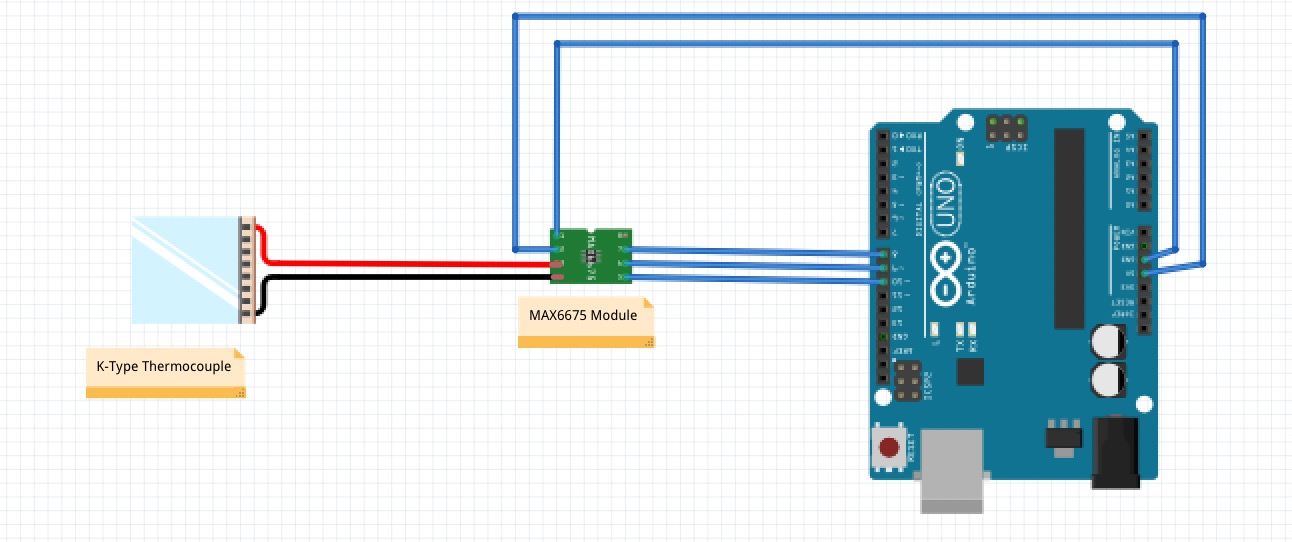
Figure 1. Schematic for Thermocouple with Max6675 Figure 2. Assembly Schematic
  Figure 3. Drawing of the Nozzle
 Figure 4. Right View of Air Straightener
- Manufacturing processes used
- We used two methods to get demanded parts, 3D print and purchase online
- 3D print: nozzle, pump/nozzle supports, air straightener and joint connecter.
- Purchase: pump, differential pressure manometer, thermocouple sensor and Arduino.
Testing/Experimentation
- Preliminary results
- Debugging and shake-down of experiment
- Make sure all the systems communicate and work
- Analysis, Discussion
- Your results may not be what you expected
- Consider why this may be the case
- If you are able to get data that can be analyzed rigorously (not expected), what methods would you use to reduce the information into generalizable knowledge?
Conclusion and Future Work
- Lessons learned
- Because of COVID-19, we experienced a distinctive lab course. In this project, we spent a lot time on choosing power supply and nozzle design. Different choices would lead various results. Under recent surrounding, we had to choose a portable power supplier and a small size nozzle. This caused actual result had a large percent error from theoretical calculation. In order to achieve ideal stage of compressible flow, we will adopt a stronger power supplier, like air tank, and a large and long size nozzle. A longer nozzle can provide an obvious pressure difference between two adjacent points.
- The most of parts were produced by 3D printer. This was a very useful and convenient facility for us to get required parts. Based on our special design, 3D printer have two advantages. First, it can print any part with any required dimension. Second, it can save time on searching fittings. Therefore, 3D printer is a strong recommended equipment for another students to use in design project.
- Next steps
- We didn’t have a chance to running this experiment, so we advise the next group of students to help us to practice this project and record data. For further work, we also advise they should change the pump to any other power supplier with fast air flow and design other tubes to replace the nozzle, so that our experiment can extend to other topics, like expansion waves, acoustic wave motion, etc.
Acknowledgments
- We would like to thank all the people who have helped us during this project, Professor George Delagrammatikas, Professor Nico Hotz, Professor Sophia Santillan, our TA Ian Eldridge-Allegra, and all of our classmates.
References
[1] R. Chandra, et al., Lab Development for Fundamental Combustion and Compressible Flow, 150 THECOOPERUNION YEARS, 2010.
[2] G. Thorncroft, et al., Modeling Compressible Air Flow in A Charging or Discharging Vessel and Assessment of Polytropic Exponent, American Society for Engineering Education, 2007.
[3] H. Krishnaswamy, et al., A Fluid Mechanics Laboratory Nozzle Design Experience, ASEE Annual Conference, 1998.
[4] R. Berg, et al., A New Approach to Teaching Compressible Flow, ASEE Annual Conference, 1999.
[5] W. Clark, et al., A Versatile Compressible Fluid Experiment, ASEE Annual Conference & Exposition, 2014.
[6] B. Linke, et al., Design and Manufacturing of Nozzles and Airfoil Shapes for Compressible Flow Visualizations in a New Engineering Course, ASEE Annual Conference & Exposition, 2017.
[7] Z. Deng, et al., Improving Teaching Technique for Outcome Based Fluid Mechanics Course at Aamu, ASEE Annual Conference & Exposition, 2007.
[8] B. Anderson, et al., A Simple Educational Wind Tunnel Setup for Visualization of Duct Flow Streamlines and Nozzle/Diffuser Boundary Layer Separation, ASEE Annual Conference & Exposition, 2008.
[9] A. Nazempour, et al., Assessments of Ultra-Low-Cost Venturi Nozzle in Undergraduate Engineering Classes, ASEE Annual Conference & Exposition, 2015.
[10] R. Mukkilmarudhur, et al., Bringing Research and New Technology into The Undergraduate Curriculum: A Course in Computational Fluid Dynamics, ASEE Annual Conference, 1998.
Appendices
- Arduino Code for thermocouple sensor with Max6675 Module
- #include “max6675.h”
- int ktcSO = 8;
- int ktcCS = 9;
- int ktcCLK = 10;
- MAX6675 ktc(ktcCLK, ktcCS, ktcSO);
- void setup() {
- Serial.begin(9600);
- delay(500);
- }
- void loop() {
- Serial.print(“Deg C = “);
- Serial.print(ktc.readCelsius());
- Serial.print(“/t Deg F = “);
- Serial.println(ktc.readFahrenheit());
- delay(500);
- }