The MEMS MS Capstone at Duke University

Drone Swarm: Search and Rescue

Drone Swarm: Search and Rescue

Abstract

Across the world natural disasters take an immense toll on humanity, causing death and destruction. Improved search and rescue techniques using drone swarms can reduce the deadly toll these disasters have. This team explored the capabilities of using computer vision with a swarm of extremely lightweight drones through a series of projects of increasing complexity.

The beginner stage thoroughly documents the process of setting up the hardware and software required for this project. Namely assembling the Crazyflie 2.1 drones, sensor selection, 3D printing usage, and setting up all necessary software.

The intermediate stage explores drone swarm flight and integrating payloads. Mainly work included the basics of flight control, multiple drone integration, communication between drones, and implementation of camera and LED payloads.

The advanced stage saw the system reach fruition with the pairing of computer vision and drone swarm flight. This work included exploration of computer vision and deep learning models for object recognition, programming various tasks based on vision outputs, and integration with the AI deck.

Lastly the expert stage puts the swarm to use on increasingly realistic tests, removing simulated portions of the system. This stage includes onboard computing, completely autonomous operation, enhanced computer vision, new positioning methods, and outdoor flight tests.

The first three stages are completed and documented in the site below, while the expert stage remains to be realized as future work. These projects are fully documented and replicable, serving as great educational resources or as a springboard for related research. These projects and relevant future work are not only useful for search-and-rescue but can be used for other applications as well. Drone swarms can revolutionize areas such as agricultural geo-mapping, military/defense, and reactive lightshows.  

Introduction

Video Description

Play Video

System Decomposition

Stage 1: Beginner

Play Video

Our project makes use of the Crazyflie 2.1 platform because of it’s unique combination of being open source, light-weight, and versatile in nature. These drones weigh only 27g, are small enough to fit in the palm of a hand, are easy to use and modify, and are great for allowing ease of experiment replication.

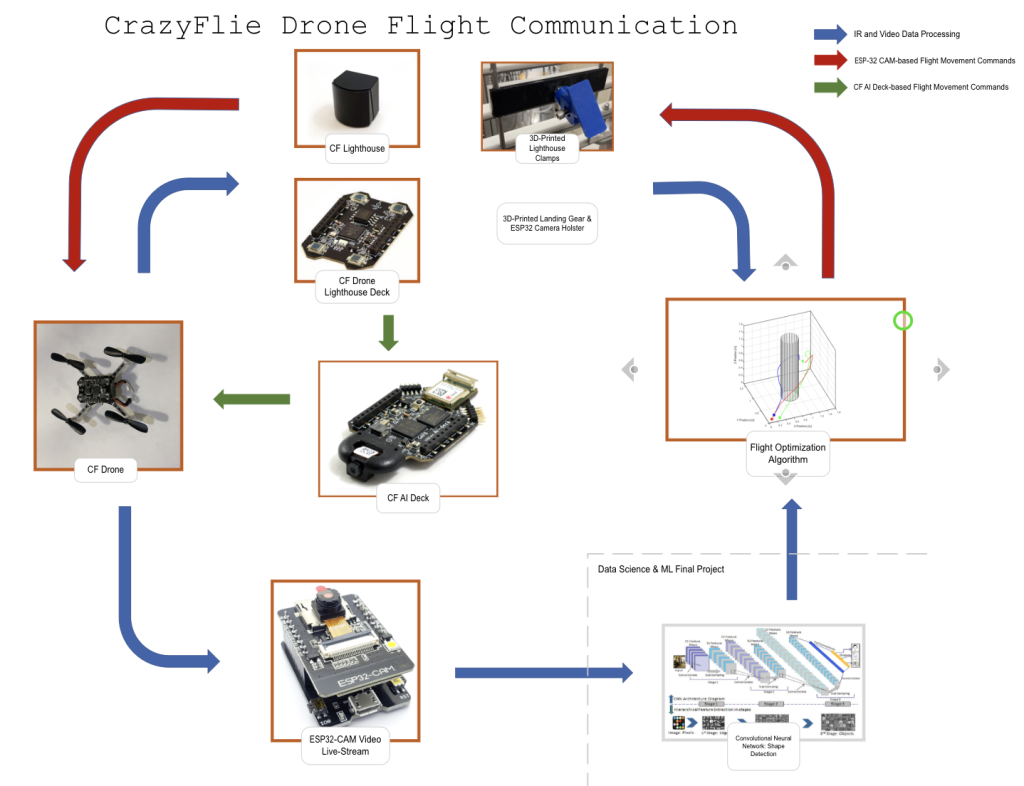
The simplest setup for control is to use one’s phone as the controller by downloading Crazyflie’s app. This provides basic controls with a small amount of tuning, but isn’t very useful for experimenting. By using the Crazyradio PA these drones can communicate with and be controlled by a ground computer. This requires downloading the CrazyFlie Client, which will be discussed in detail in the following section. With radio in place the CrazyFlie drones can be controlled via a gamepad, keyboard, or via code.

To fly autonomously however, without a human using a gamepad or other controller, there must be some sort of positioning system for the autonomous program to determine where the drone is. Bitcraze, the makers of Crazyflie, offer many positioning system options. Their options can be categorized as either absolute positioning, where the controller knows the location of the drone compared to a set defined origin point, or relative positioning, where the controller makes decisions relative to the drone being the origin. An additional category is whether pose estimation happens on board the Crazyflie or off board on a computer. For our project we wanted an absolute positioning system to be able to interact with objects, avoid obstacles, and generally fly around a set environment. We also wanted the capacity for on board pose estimation for higher fidelity towards a final product while also minimize the load on the computer likely to be running an image processing algorithm.

This left us with two options that met both those needs; the Lighthouse positioning system or the Loco positioning system. The Lighthouse system is optical-based, with two or more base stations sending out IR signals that get picked up by receivers on the drone. This allows for very precise positioning indoors for a fraction of the cost of motion capture methods while still enabling on board position acquisition. The Loco system uses ultra wide band radio to communicate between many ground stations and the drone, not unlike a miniature GPS system. Based on our needs for precision and repeatable testing we chose to go with the Lighthouse positioning system.

We then took the following steps to set up the CrazyFlie drones.

  1. Test the Crazyflie before beginning assembly to ensure it wasn’t damaged in transit.
  2. Assemble the Crazyflie using the recommended instructions, making sure to use care not to break any components during the process.
  3. (Optional) If desired, download the Crazyflie app on from either Apple or Google stores, connect the battery wire to the Crazyflie, turn on the drone, pair with your phone, and conduct test flights.
  4. Remove the battery holder board and replace with the Lighthouse deck.
  5. Repeat steps one through four for any remaining drones in your swarm.

At this point the Crazyflie drones are ready for use with the Lighthouse base stations. The remainder of this mostly virtual setup will be covered in the following Crazyflie Client section.

-Patrick

Cfclient is the official open-sourced python-based software for the Crazyflie system. It plays a vital role in this project. Read more!

There were two main hardware design needs for this project. First, the Lighthouse basestations needed a custom mounting system to remain locked in place in our test setup. Second, the Crazyflie drones needed to carry an ESP-32 CAM payload they weren’t designed for. 

Lighthouse Basestation Mount:

The Lighthouse Base Stations have a threaded hole for being secured, but the included mounts did not meet our needs. We decided to pursue the design of a custom mount, and this design process is documented in the video below.

This led to the final setup pictured below. This consists of the two identical 3d-printed mount pieces, the two 3d-printed hinge parts, 2 3/4 in. #10-24 screws, 2 #10-24 nut, another 3d-printed part that screws into the lighthouse is superglued to exposed face of the 2nd hinge part. This design process was necessary for us to test the system properly and enabled much of the work shown on this website.

3D-printed components screwed onto a slatted cage wall.

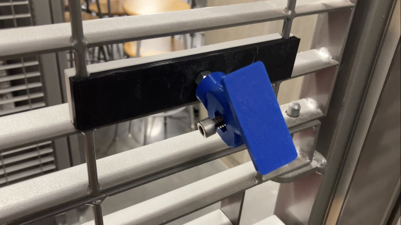
Custom Lighthouse mount 3d-printed and assembled.

Camera Mount:

The second hardware design challenge was of a very different nature, relevant to the project directly via being on-board a drone: making a custom camera mount. This challenge proved difficult most of all due to weight constraints, as although the Crazyflie aerial robots are very versatile, they are ultra lightweight and have very little payload allowance while still being able to lift off the ground and maneuver. The video below dives into this process, specifically how to fit the ESP-32-CAM module onto a Crazyflie drone in a manner that was secure, removable, and under-weight. 

This process resulted in a successful payload mount, cutting in at just under 3 grams for the 3d-printed material, and images of what the system looks like integrated with the drone and camera can be seen below.

3d-printed parts

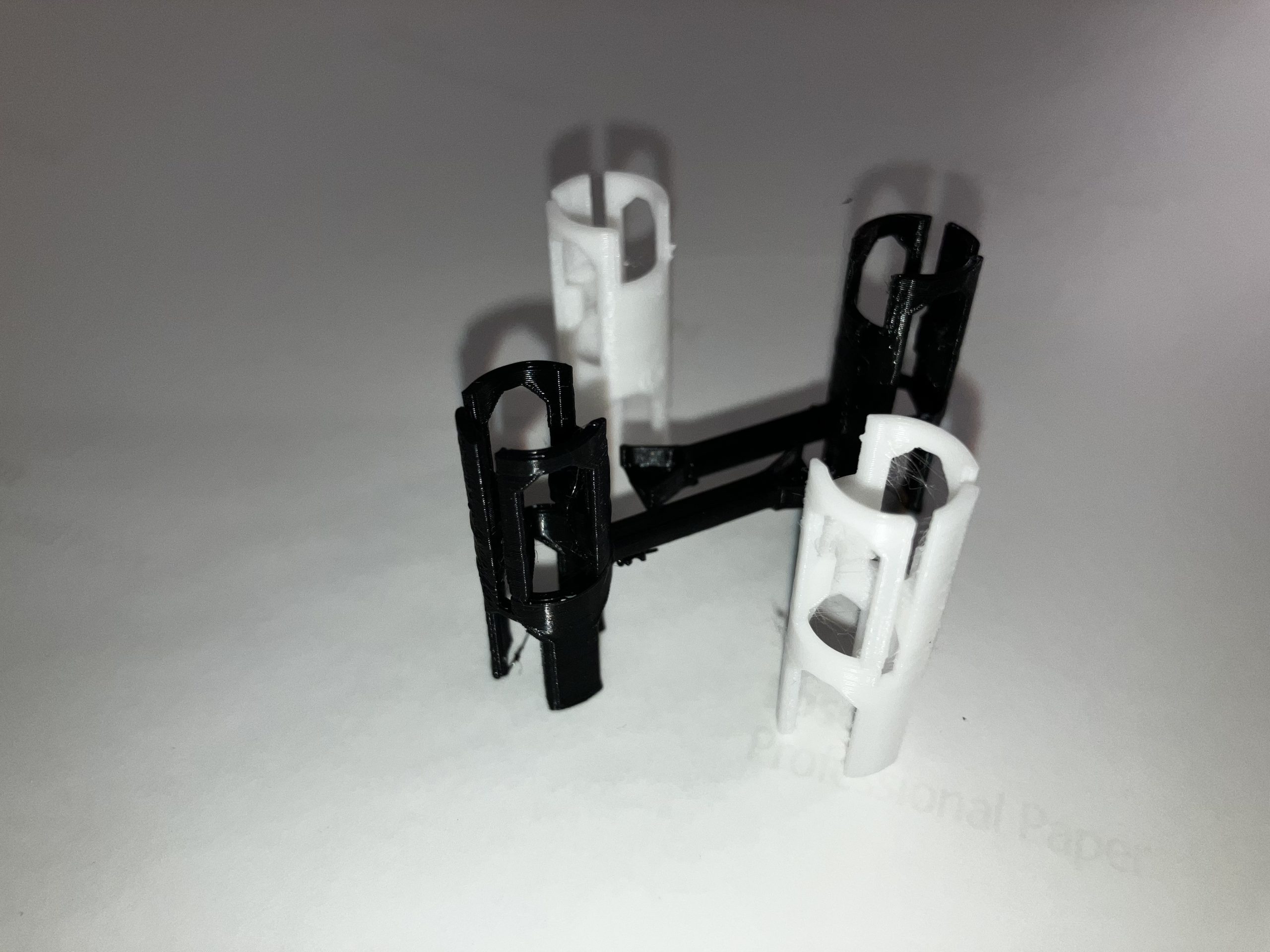
Four 3d-printed mounts, both with and without support arms for the ESP-32-CAM.

drone with camera payload propped up to one side.

Crazyflie and mounts with camera payload propped up for display to one side.

Small drone with camera attached beneath it

Crazyflie with camera payload fully set up and ready to fly.

 
-Patrick

Stage 2: Intermediate

Play Video

Understanding how the drones can fly and be controlled is the foundation of this project. If you are interested, we have a quick tutorial that walks you through the principles of what makes a drone, a drone. Read more!

How the team set up their experiment lab space for this project, and what to look out for. Read more!

Control multiple drones at the same time is more than a collection of controlling many ones one-by-one. Read more!

Stage 3: Advanced

Below is a short demo of the final result as this project concluded, with swarm drone flight and neural network based computer vision. Anyone can pick up where we left and build more on top of it!

Play Video

Although we used the ESP-32-CAM for this project, there is a better camera option for the Crazyflie system. The AI Deck that Bitcraze produces not only has an integrated camera of better quality than the ESP-32-CAM, it also enables on-board computing of ML algorithms. 

The AI Deck has many benefits over the ESP-32-CAM. First is the easy integration with the drone swarm. Each Crazyflie can stack two “decks” on top of the battery using the long pins included with each Crazyflie 2.1. By simply putting the AI Deck underneath the Lighthouse deck, with the camera facing the front of the craft, the physical setup is fully complete. This saves the time and effort of custom mount for integrating the ESP-32-CAM as well as saves any challenging wiring problems. Once physically installed the software setup is also simple, and importantly is clearly documented by Bitcraze

Another major advantage is a better camera, which leads to better image quality and makes for an easier time creating the algorithm and less pre-processing of each image needed. The deck features the 324 x 324 pixel Himax HM01B0-ANA color compact camera module, which is Ultra Low Power (ULP), and has high sensitivity.  The most important feature is the AI Deck’s camera having an automatically focusing lens, with automatic exposure and gain control loop, while the ESP-32-CAM has only a manually-adjustable lens and generally poor focal length for anything past close distances.

The last major advantage, and what makes the AI Deck a must-use for any future work, is how it enables onboard computing. This is the main feature of the deck actually, with camera being secondary to the GAP8 IoT application processor. This processor improves the on-board computational capabilities such that complicated AI-based code can be run on the Crazyflie with no need for a ground station computer. In fact, this setup enables truly fully autonomous navigation and operation. A paper out from researchers at ETH Zurich explores using the AI Deck and provides even more documentation of usage.

More about onboard computing using the AI Deck, including sample code for object recognition and computer vision, will follow in the Expert portion of this project.

-Patrick

Stage 4: Expert


The final stage of our project is the Expert stage. These portions of the project remain future work, if you are reading this and have  been intrigued with our work so far feel free to replicate our progress and tackle one of the following Expert-level tasks. These tasks each provide a challenge that proves mastery of multiple technical disciplines and would be worthy of documentation or even a peer-reviewed paper. 


Task 1: Onboard Computing

The first Expert task is implementing onboard computing. The drone swarm system up the this point is relying on the ground station to provide computing power to run the algorithm for computer vision, movement planning, and action decisions. With the integration of the AI Deck, now the Crazyflie is capable of completing all necessary computation on-board the aircraft. This section explains the steps that would be necessary to demonstrate onboard computing effectively and gives some sample code of what can be uploaded and run on the AI Deck.

Task 2: Improving Object Recognition Model

The second Expert task is improving object recognition and Deep Learning models. This task is about mastering use of machine learning to implement object recognition in a way that would be useful in the real world. Taking the shape recognition previously described on this site and moving on towards recognizing signs of human life, such as a human face or body. Additionally this task features a deeper look at deep learning models and how to modify them to reach their maximum effectivness.

Task 3: Outdoors Testing

The third Expert task is to swap to outdoors testing effectively. This task, while simple sounding, may be the most challenging of the bunch. There are many components of the current system that cannot function outdoors between the sunlight IR interference, battery life concerns, and communication range limitations. In solving these challenges this task brings the project to a much higher fidelity level, closer to the final use case and saving lives.

Task 4: Implementing Model Predictive Control (MPC)

MPC is a very advanced form of a process control method and is useful due to the efficiency it brings. The method is more efficient due to acknowledging the resource that is time and planning around future timeslots while optimizing the process in the current moment. By implementing MPC this project will be higher fidelity and closer to use in the field.

Task 5: Hardware Integration of Camera and LEDs

Within the time constraints of this semester, our team has managed to build a robust object detection model with the ESP32-CAM and displayed. the concepts of its subsequent drone actions through LEDs. However, we could not attach the camera and LED to the body of the drones due to payload and battery supply constraints. We hope that the next team who takes on our work can tackle these limitations.

– Patrick & Paavana

Computing resources are always precious, especially so for these mini drones. But we can still get some of that onboard, and put it to good use. Read more!

Throughout the project, the accuracy of shape detection has been prone to lighting, focal distance, and resolution of the camera. To aid in the full system integration, the shapes provided for detection were basic and had distinct color variance between the shape itself and its surroundings. In the future, however, by utilizing higher-resolution cameras and more accurate classification models, the shape detection model could improve its accuracy.

As mentioned in the “Onboard Computing” section of the Drone Swarm portfolio page, the CrazyFlie AI deck would improve the camera quality and power of the shape detection model. This camera receives images 320×320 pixels in a grayscale format for best results in its classification. To process images at this size, the AI deck then uses on-board, artificial intelligence-based programs to analyze the frames depending on the tasks at hand. This AI deck also includes the same Wi-Fi connectivity as the ESP32, therefore would have a similar image extraction process within a Python codebase.

The classification model utilized in this project relied on the shape detection program previously created by OpenCV, however these images could be sent into a machine learning model instead. In particular, utilizing a ResNet artificial neural network to detect specific objects or shapes would increase the accuracy of the classification model. With a convolutional neural network uploaded to the on-board processor for the AI deck, the drone increases its self-autonomy and power. By continuing to investigate the self-autonomy of a search and rescue drone, we can look to save innocent lives with the assistance of intelligent technology.

CrazyFlie AI Deck Specifications

Another major challenge left as future work is to make the system able to function outdoors, and verify that capability with a successful outdoors flight test. This task, while simple sounding, may be the most challenging of the bunch. There are many components of the current system that cannot function outdoors between the sunlight IR interference, battery life concerns, and communication range limitations.

For example, using the Lighthouse positioning system is impossible outside a laboratory setting. As a positioning system it requires set base stations above the test site, which is difficult to set-up outdoors besides the fact such a set-up would be impossible in actual search-and-rescue scenarios. Additionally the Lighthouse method features too small of a range to be very effective, and suffers from sunlight interfering with IR communication. The easiest to implement form of positioning would be GPS, although this is inaccurate for precise maneuvers. It is possible a combination of GPS for general positioning and another method for relative positioning to other drones in the swarm could work. Alternatively a more precise positioning method that does not require ground stations could be found.

Another concern is long-distance flying. Battery life is a major constraint since the Crazyflie swarm can only fly for about 10 minutes before needing to re-charge. Another factor is communication, as some communication with a ground computer must happen to alert rescuers when someone is encountered. The Crazyflie PA radio has a range of up to 1km in ideal conditions, but the system must work in the worst conditions and would likely require longer range for some missions. For these reasons it is likely a new drone swarm platform would need to be found for long range outdoors use.

In solving these challenges this task brings the project to a much higher fidelity level, closer to the final use case and saving lives.

-Patrick

MPC is very necessary if we want the swarm to perform more complicated tasks in more sophisticated ways. That, or distributed multi-agent reinforcement learning. Read more!

Conclusion

Earthquakes and other natural disasters cause immense devastation worldwide; improved search and rescue techniques can reduce this toll. This team has set the stage for future research toward that goal by using computer vision with a drone swarm to trigger reactions and guide actions. We explored four stages of tasks to accomplish this goal, ranging from beginner to expert. The first three stages were completed, while the expert stage remains to be realized as future work. While our work does not directly help rescue efforts today, it sets up further research that will reduce the time taken by first responders to act and will lead towards more lives saved at the time of a disaster. This project and direct future work can also have further applications for our world, ranging from reactive lightshows to agricultural geo-mapping.

Acknowledgements

First and foremost, an enormous thank you goes to our Professor George Delagrammatikas. We couldn’t have completed this project without his sage advice at all stages. Additionally we thank our classmates for their feedback throughout the semester. Lastly we want to thank the Thomas Lord Department of Mechanical Engineering and Materials Science, Pratt School of Engineering, and Duke University for enabling this course.