Designers:Daniel Li and Raiyan Sobhan
Advisor: Melissa Werz, OT, Steve Reznick, Ph.D.
Supervising Professor: Kevin Caves
Abstract
ALS is a progressive, neurodegenerative disease that afflicts many people in the United States each year [1]. Our client who has ALS displays many of the  common symptoms of the disease. Our client wishes to continue his passion for playing the harmonica, but the disease limits his ability to play the harmonica independently. Our goal was to design a device that can hold harmonicas up and into our client’s mouth, switch between 4 harmonicas, and easily move towards and away from our client so that he may be able to regain his ability to play the harmonica independently. Our device, the “Harmonicator” meets these requirements by utilizing a simple remote with buttons that allows our client to adjust the positioning of the harmonica and switch between multiple harmonicas. The device was tested both in the lab and with our client to ensure that the device meets our design specifications and safety requirements. Overall, the device enables our client to be able to play the harmonica much more independently.
Introduction and Background
Our client is an adult man with amyotrophic lateral sclerosis (ALS), also known as Lou Gehrig’s Disease. ALS is a progressive neurological disease with largely unknown causes that attacks motor neurons in patients [1]. Our client presents with common symptoms of the disease: he cannot reliably lift his arms or legs, and instead uses a wheelchair to move around. He has full cognitive abilities. At this point, he can still move his fingers with limited dexterity. While our client can currently speak without difficulty, move his neck with a full range of motion, and use his fingers with a fair amount of dexterity, these abilities may degenerate in the near future.
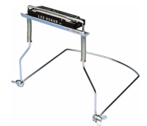
Figure 1: Lee Oskar harmonica holder
Our client has been a lifelong, avid harmonica player. Currently, he uses one of many available stands, such as the Lee Oskar Harmonica Holder [2] (Fig. 1), that holds harmonicas up to and into his mouth. However, this stand strains our client’s neck and is very difficult to independently move towards and away from his mouth. In addition, our client’s current stand can only hold one harmonica at a time. Harmonicas are tuned to only one key – many songs require the use of multiple other harmonicas that other musicians can simply grab with their hands. To solve these problems, our client needs a device that allows him to accomplish these tasks without requiring him to move his arms.
Project Goals
The goal of our project is to develop a device that can hold harmonicas up and into our client’s mouth, be able to switch between 4 harmonicas, and easily move towards and away from him. Our client must be able to independently complete all of these actions by himself without moving his arms. The device should also be designed to be comfortable and simple to use.
Design and Development

Figure 2. Harmonica Spinner. The components that make up the harmonica spinner: harmonica plates (with wing screws and magnets), the threaded rod, the bearing, and the motor
To allow our client to move harmonicas into his mouth without needing to lift his arms, we needed to construct a stand capable of stably holding harmonicas at his mouth level while he is sitting in his wheelchair or desk chair. The stand would need to hold up four harmonicas and have some mechanism of switching which harmonica was at the playing position. Finally, our client would need some way to control the entire device without lifting his arms from his lap.
The device is comprised of 3 main components: the harmonica spinner, the stand, and the user remote and controls circuitry. The spinner holds harmonicas in proper playing position and allows our client to rotate one of 4 harmonicas into his mouth. The stand holds the harmonica spinner up and can rotate the spinner into and away from his mouth. The user remote has several buttons with which our client can control the movement of the entire device. These portions are described in detail in the following sections.
Harmonica Spinner

Figure 3: Harmonica Stand. On the left are the components that make up the harmonica stand: tripod, hook, 3D-printed platform, C-channel aluminum rod, gears. On the right is a close-up of the gear system
The harmonica spinner (see Figure 2 below) holds 4 harmonicas in place using two 3D printed plates. Slots protrude from the plates, each of which contains an embedded magnet on a single side. The opposing side of each magnet has an adjustable wing screw with a cap on the end; tightening and loosening this screw allows the spinner to fit harmonicas of several thicknesses. These plates and slots allow the harmonica to be held stably in place both by magnetic attraction and pressure from the screws and caps. The wing screws can easily be turned to allow our client’s caretaker to slide the harmonicas in and out of the device.
The spinner apparatus is connected together with a long threaded rod. Locking nuts hold the plates in place along the rod. One end of the rod is pressure fit into a bearing while the other end is connected via a shaft collar to a small stepper motor. The motor is controllable from the user remote, which has buttons that allow fine-adjustment movements clockwise and counterclockwise as well as fast 90º turns.
Stand
The stand is constructed primarily from a modified camera tripod (see Figure 3 below). The main purpose of the stand is to ensure that the device does not tip over while holding the spinner up to our client’s mouth (approximately 45” above the ground).
On top of the tripod, where the camera platform would normally belong, is a 3D-printed platform which holds the moving parts of the device. One side of this platform holds a large stepper motor in place. The other side of this platform holds a bearing which connects the piece to a large 3D-printed gear. This large 3D-printed gear is attached to a long, aluminum, C-channel rod that holds the spinner apparatus. This gear can be rotated by the small gear attached to the large stepper motor (see Figure 3 below), controllable from the user remote. Together, these pieces allow our client to rotate the harmonica spinner into his mouth for playing and to completely rotate the spinner away from him while the device is not in use.
The stand height can also be adjusted by our client’s caretaker through either the shaft crank located at the top of the device or by extending or shortening the tripod legs. The stand also has an attached hook at the bottom of the central column. A small amount of weight (less than 5 lbs) attached to the device by this hook significantly improves the device’s stability.
User Remote and Controls Circuitry
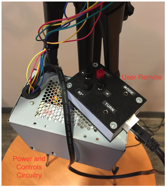
Figure 5. User Remote and Power and Circuitry Box. The Arduino (inside the box) takes commands from the user via the buttons on the remote and executes them to the motor controllers
The device is controllable from a small user remote with several buttons (see Figure 4 below) which our client can use from his lap. The ‘’mode’ button can be used to switch which motor our client is controlling. The two buttons below ‘mode’ will, when pressed, rotate the chosen motor clockwise or counterclockwise. Below these buttons is a button called ‘90º’, which when pressed will quickly rotate the harmonica spinner by 90º. When our client wants to switch harmonicas, he can press the 90º button until he is near the harmonica that he wants to play. If he started from another harmonica, just pressing the 90º button will get the new harmonica perfectly in position. However, if he started out of position, he can use the clockwise and counterclockwise buttons to finely adjust the positioning of the spinner.
In addition, the user remote has two input slots for audio jacks. These inputs allow our client to connect an auxiliary button or switch to control the device. The ‘mode’ input is designated for a button that changes which motor the user is controlling. The ‘turn’ input is designated for a button that turns the chosen motor clockwise or counterclockwise. Each subsequent activation of the ‘turn’ input will rotate the chosen motor in the opposite direction from the previous.
Commands at the user remote are sent to the power and circuitry box (see Figure 5 below) to the microcontroller on the Arduino Nano. The Arduino sends these commands to the appropriate motor driver, which will move the motors. A Mean Well 12V power supply provides power to the Arduino and the motors. Both motor drivers have attached heat sinks to prevent overheating when using the device for an extended period of time. Full circuitry schematics are included in Appendix B.
The user remote is connected to the power box via an ethernet cable, which can be detached from the remote when the device is no longer in use. The entire device must be connected to a standard wall outlet (110VAC, 60Hz) to function via the power cable. The power cable can also be detached from the device via the power interface slot on the bottom surface of the power box.
Evaluation
We evaluated our device against our initial design specifications (reproduced in full in Appendix C) and their verification and validation plans. Broadly, the design specs could be separated into device functionality, stability, versatility, and comfort. Device functions – moving the device and switching between instruments – were verified during bench testing of the components that we chose and then validated through testing with our client and through the satisfaction survey. Stability was evaluated through several quantitative experiments as well as testing with our client to ensure that our device was well within satisfactory bounds for our client. Versatility and comfort were evaluated by testing with our client and through the satisfaction survey. We also completed quantitative analyses to evaluate the safety of our device, such as tipping. Our client indicated, both through the satisfaction survey and verbally to us, that he was extremely satisfied with all aspects of the final device. He felt confident that the device would do everything that he wanted and even possibly help him improve his diaphragm function.
Discussion and Conclusion
We were able to successfully design, fabricate, and assemble our device to meet all of the needs of our client as described in our initial problem statement. Verification during bench testing and, more importantly, extensive client testing demonstrated that our device satisfied the functionality, stability, versatility, comfort, and safety requirements. We and our client believe that this device will help him to play his harmonicas for much longer than his muscle weakness previously allowed him to. The device is also unobtrusive and aesthetically pleasing; our client indicated that it would be a welcome addition to his home. Our device’s success was best summed up by our client when he said, “You’ve accomplished everything you set out to do.”
Acknowledgements
We would like to thank our primary mentor, Professor Kevin Caves, for his support and guidance throughout all stages of our project. We would also like to thank Matt Brown, Steve Earp, Greg Bumpass, and John Goodfellow for their technical advice on the project. Additional thanks is given to National Science Foundation grant CBET 3310005 for providing funding for our project. Lastly, we would like to thank our client and his family.
References
- National Institute of Health: National Institute of Neurological Disorder and Stroke, 2016, Retrieved February 8, 2016 from http://www.ninds.nih.gov/disorders/amyotrophiclateralsclerosis/detail_ALS.htm
- Musician’s Friend. Lee Oskar Harmonica Holder. Retrieved February 8, 2016 from http://www.musiciansfriend.com/folk-traditional-instruments/lee-oskar-harmonica-holder?cntry=us&source=3WWRWXGP&gclid=CO3_ptn66MoCFQJZhgodndkPVQ&kwid=productads-plaid^140837317461-sku^423607000000000@ADL4MF-adType^PLA-device^c-adid^92666429307