Designers: Ryan Denkewicz, Hersh Lakdawala, Boying Shui, Kavin Vasudevan
Client Coordinator: Roger VanDyke
Supervising Professor: Larry Bohs
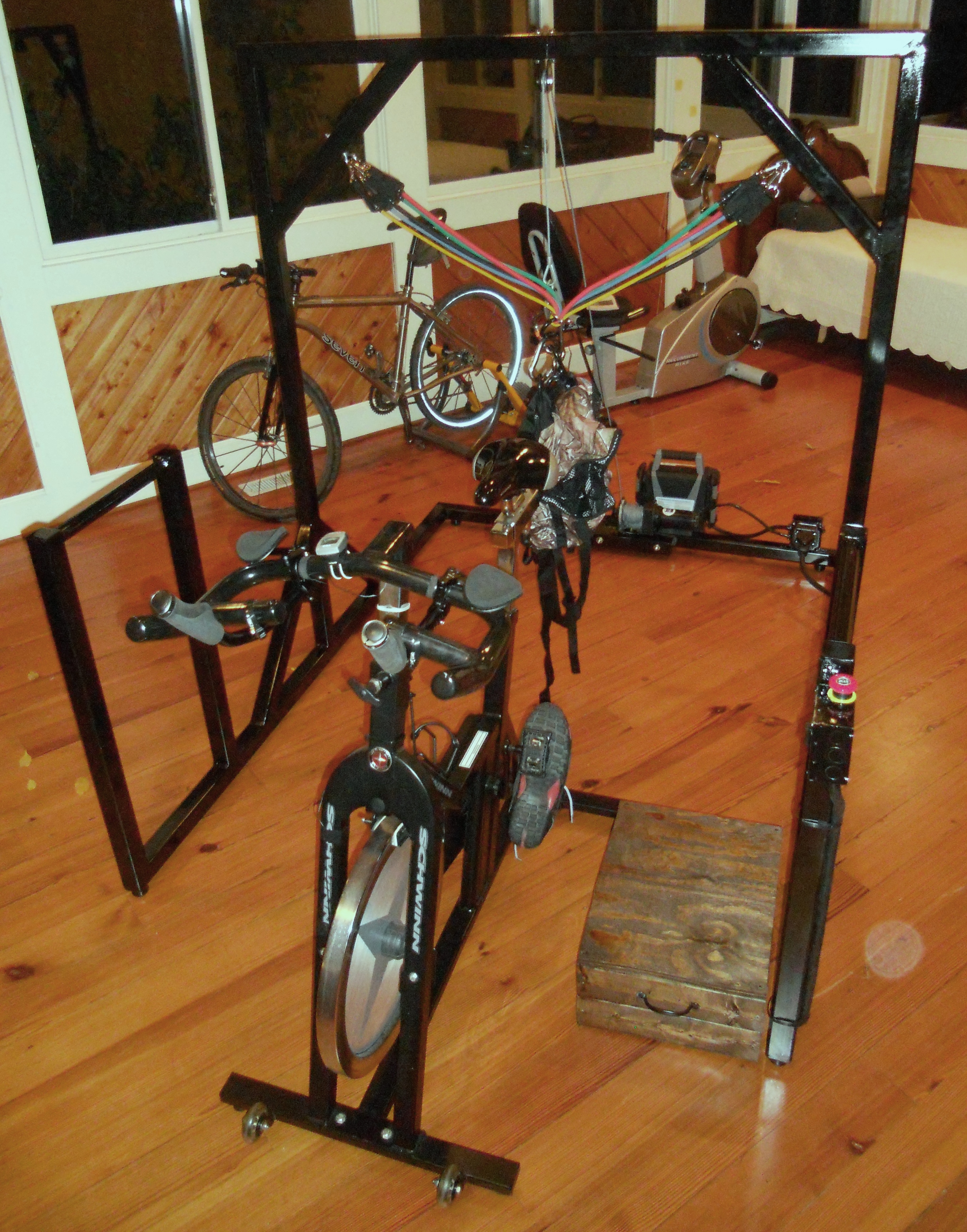
Figure 1. Spin Solution.
INTRODUCTION
Prior to being diagnosed with a form of multiple sclerosis that severely restricted his mobility, the client was an avid cyclist who biked over ten thousand miles per year. The goal of this project is to assist him in riding a stationary bicycle with the long-term goal of building enough strength to cycle outdoors unassisted. The Spin Solution includes a steel support frame, a harness that provides variable core and lateral support, a winch that helps with mounting and dismounting, and an ergonomic armrest to alleviate the load on the client’s left hand. The device provides stability, graded support, and comfort, allowing the client to train indoors to gain strength.
SUMMARY OF IMPACT
The Spin Solution supports the client’s core, distributes his upper body weight along his arms, and ensures that he stays mounted on the bike. The client has been using the device regularly for conditioning. Based on this, he has transitioned to an outdoor trike. He comments, “The professionalism and dedication demonstrated by the students enabled me to get in shape and get back on my trike, and begin to ride outside again. I have ridden 57 miles on my trike so far this week, my new record. I couldn’t have done it without my winter conditioning program with the Spin Solution.”
TECHNICAL DESCRIPTION
The Spin Solution comprises a steel support frame, a power supply (Peak PKC0AZ 4), a 12V winch (Superwinch Model 1215200) with attached cable and hook, a 7-way RV power connector (Hopkins), an industrial grade pulley (5RRR1 Block), a 30-amp DPDT rocker switch, a self-locking emergency stop button, a set of resistance bands (Black Mountain), a harness (Ameristep climbing vest), and aero handlebars (HB Aero Evo Extensions).
The 80” x 60” x 68” frame is made from welded 2.5” square steel tubing, coated with black epoxy paint to prevent corrosion. The frame incorporates 36” high handrails at the front of the support system. A separate 8” wooden step assists the client in mounting the bicycle.
The winch is bolted to two blocks of 2”x2”x12” high-density polyethylene (HDPE), which are bolted to the rear crossbar at the base of the frame. The pulley is bolted to the center of the top crossbar of the frame. The winch cable runs through the pulley such that the cable can be freely extended and retracted.
The power supply plugs into a standard 120-Volt outlet. The 12V DC output of the supply connects in series to both the emergency stop button and the toggle switch, which are housed in a 4” x 4” x 2.25” junction box. The emergency stop button removes power from the winch when depressed and resets by twisting clockwise. The toggle switch changes the polarity of the power source provided to the winch, triggering either extension or retraction of the cable.
For ease of assembly, the battery and winch are connected to the male terminal of the RV connector. The female terminal is housed in a 4” x 4” x 2.25” junction box that mounts to the rear of the frame. When the male terminal is unplugged, the battery and winch can be transported separately from the frame, simplifying the transfer and reducing the risk of damaging the wiring.
A carabineer attaches the harness to the winch through a belt of nylon webbing at the upper-back of the harness. The harness includes five straps for load distribution: a buckle that secures the lower abdomen, a seatbelt strap that fastens at the stomach, and three Velcro straps. One Velcro strap distributes load across the upper chest area, and two straps distribute load across the lower abdomen. Five resistance bands feed through a carabineer at the back of the harness and connect to the frame via eye bolts on the frame. Individually, these resistance bands offer two to thirty pounds of resistance, and are used together to offer graded lateral and core support. The user can thus adjust the degree of support to his current needs, reducing support as he regains strength.

Figure 2. Client using the Spin Solution.
The combination of harness, resistance bands, and winch provides both variable support and a fail-safe mechanism. The elasticity of the resistance bands creates a more natural riding experience by allowing some lateral freedom of movement, while the winch sets a hard stop that prevents the user from falling forward.
The aero handlebars clip to the spin bike handlebars using metal clamps. The rubber coating on the spin bike handlebars is removed and a layer of bike wrap ensures that the aero handlebars grip tightly. For additional support, zip ties secure the aero handlebars to the spin bike. Adjustable foam armrests allow the client to distribute his upper body weight along his forearms. The armrests are set to accommodate the limited range of motion of the client’s left arm. Ergonomic handgrips at the end of the aero handlebars contribute to the client’s continued comfort during long cycling sessions. The replacement cost of the Spin Solution is $1,360, including $700 for constructing the frame.